Language: 日本語 | English
Language: 日本語 | English
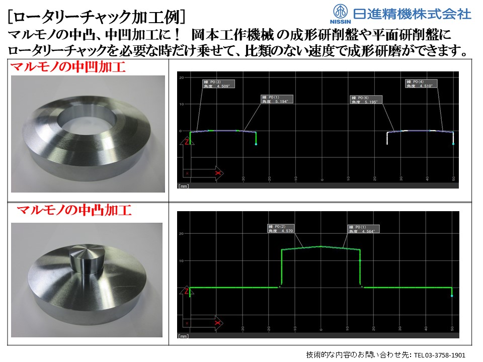
For customers struggling with convex/concave round workpieces or micron-level precision grinding, the Nisshin Rotary Chuck is the ultimate solution. This high-precision rotating electromagnetic chuck is designed to enhance grinding efficiency and accuracy.
Developed by our company—a precision press die manufacturer with over 60 years of history—this in-house product was originally created to dramatically streamline our own grinding process. Now, we offer it for sale to fellow metalworking and press processing companies.
Simple & Efficient Add-On
Attaches and detaches easily onto the chuck surface of your existing sine bar chuck or tiltable chuck in small profile grinders or surface grinders.
Perfect for low-volume, high-mix grinding operations, providing flexibility and efficiency.
Proven Applications
Silicon wafer sub-micron grinding
Reduced grinding time for ultra-hard components
The Nisshin Rotary Chuck is a game-changer for precision grinding, helping manufacturers achieve higher accuracy and efficiency with minimal setup effort.
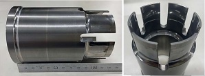
This high-precision punch component is specifically designed for blanking die applications. It is made from HAP40, a material known for its high hardness and excellent wear resistance, and achieves a precision of ±0.03 mm.
At Onuki Manufacturing, we specialize in precision component machining, including cutting processes. We flexibly accommodate one-off custom parts as well as small-lot production.
“ I have a drawing, but I’m not sure where to place the order…”
“ I only need a small quantity, but high precision is required…”
If you have concerns like these, please feel free to contact us for a consultation!
With many years of experience and proven technical expertise, we are committed to supporting manufacturing that closely meets our customers’ needs.
~ Other technologies and products ~
[Cold Forging]
https://ja.nc-net.or.jp/company/34417/product/detail/263212/
[Plate Forging]
https://ja.nc-net.or.jp/company/34417/product/detail/124331/
[Square Deep Drawing]
https://ja.nc-net.or.jp/company/34417/product/detail/124323/
[Deep Drawing]
https://ja.nc-net.or.jp/company/34417/product/detail/124327/
[Copper Terminals & Busbars]
https://ja.nc-net.or.jp/company/34417/product/detail/124971/
[Laser Welding]
https://ja.nc-net.or.jp/company/34417/product/detail/263177/

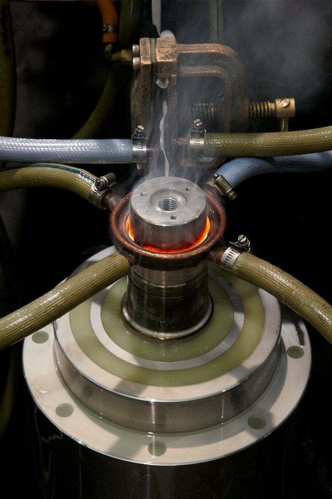
The product shown in the picture is a cut sample of a small diameter precise ball screw.
The bottom (diagonally right) product has been processed using an ordinary quenching technique.
The top (center) product’s appearances are exactly as before processing.
However, inner portion is quenched completely.
As one can see, our “non-oxidation quenching” will not cause any scale as ordinary quenching.
This method requires no after treatment as shot blast.
In other words, scales and sands which can cause reduction of after treatment preciseness will not be problematic.

We sale high frequency induction heating machineries.
This machine will utilize the induction heating principle which has effects on improving surface hardness and improved wear resistant.
【Advantages of the Induction Heating Quenching】
・Shorter lead time → Reduced processing steps
・Efficiency → Lower electricity usage, aka energy saving
・Heat when needed → A small lot manufacturing
・Partial Quenching → Partially quench depending on the shape
・Only require electricity → Ecological (no smoke and/or gas emission)
・The product will generate heat → Heat efficient
・Easy to in-line
In addition, our manufacturing section produces products on commission.
Also gladly handle a small lot orders, complicated shapes, and/or first time quenching for the specific product.
Feel free to contact us.
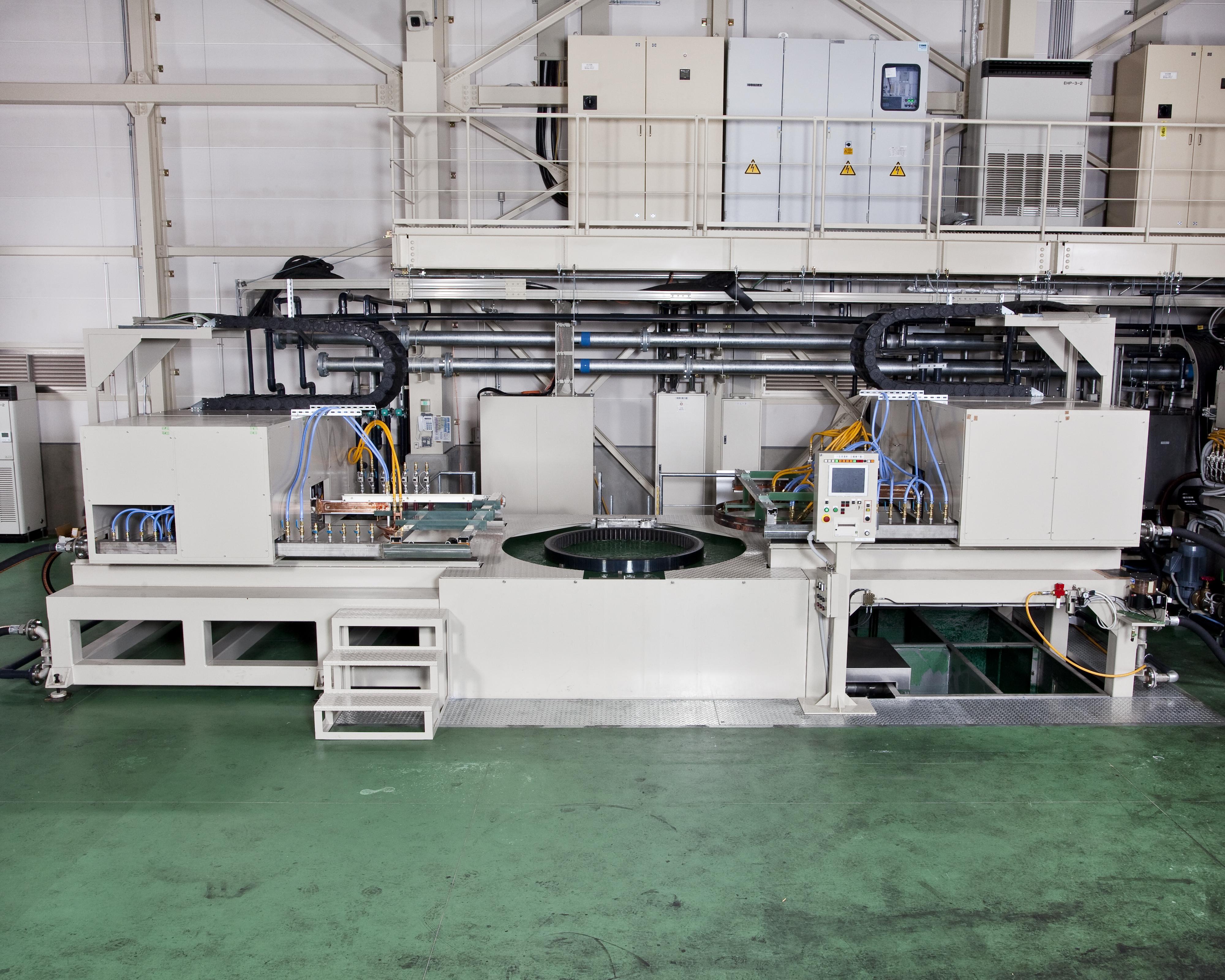
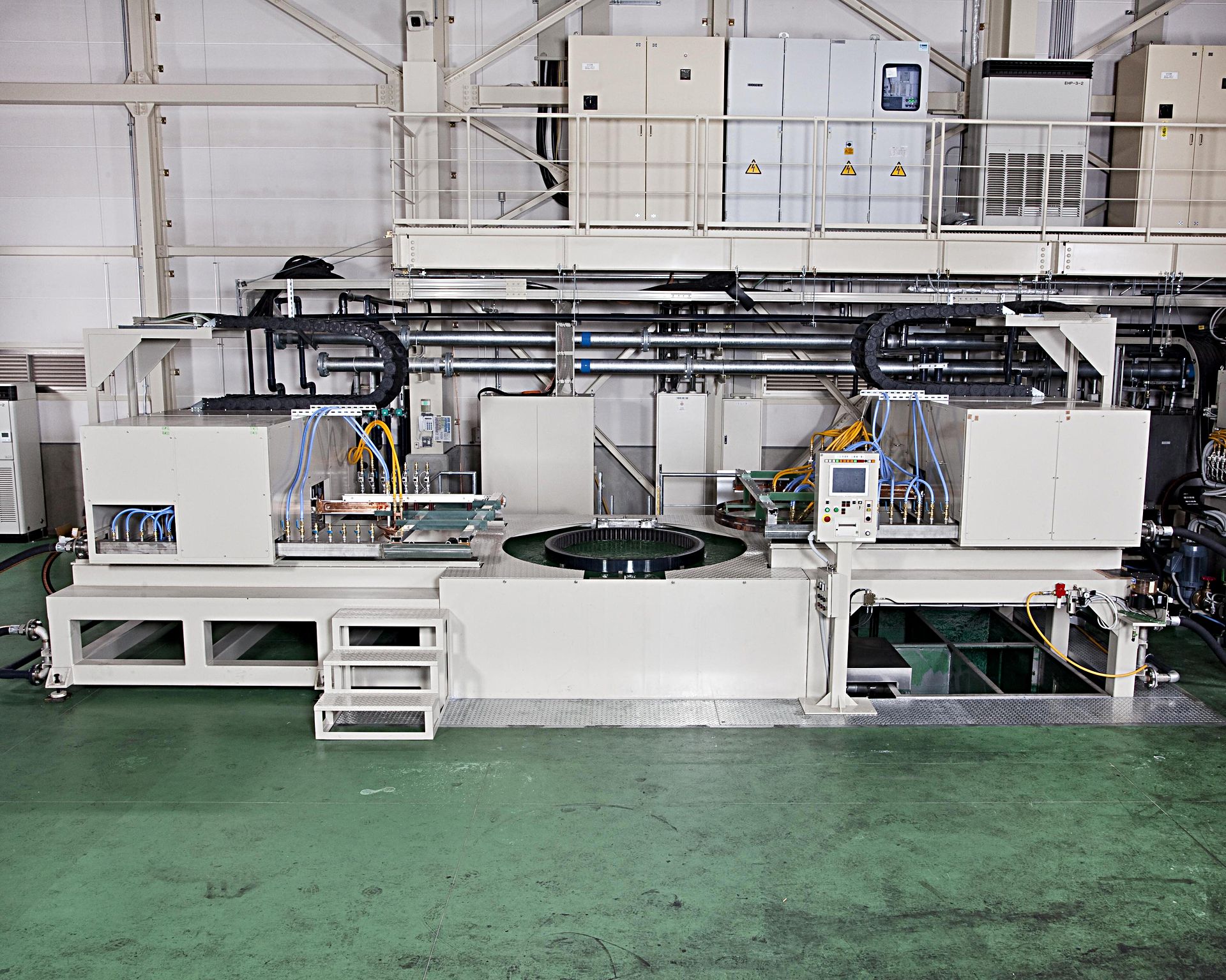
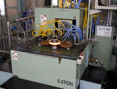
In house assembled oversize carburizing machine.
[Main Product] Bearing race, large size internal gear, large size gear
✔ Max. φ1800×(H)400mm
[Material] Carbon steel (S45C), Stainless steel (SUS304)
[Single Quench]
For transfer quenching, starting and ending point of heating and cooling overlaps leading to cracks or reduced hardness.
With Fuji Electronic all around single shot quenching, a complete uniformed quenching layer can be produced even a slewing ring size of diameter of 1.8m and module of 15. Also, comparing to transfer quenching, improved productivity, 1/5 work speed, and 1/2 ~ 1/3 electricity consumption.
[Carburizing]
Once the heating process has completed, by simultaneously dipping the product into the cooling water and blasting water current through jackets, helps to prevent from entering while forming a uniformed quenched layer.
In addition, by controlling quenching water temperature and stir speed, an effect layer can be controlled precisely.
[Inner and Outer Diameter Simultaneously Heating]
By having two electrical switches on both sides, the inner and outer layer can be quenched simultaneously with low distortion.
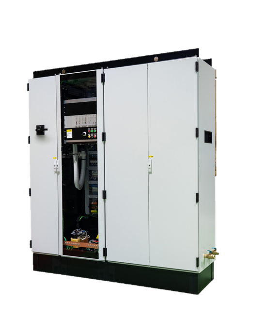
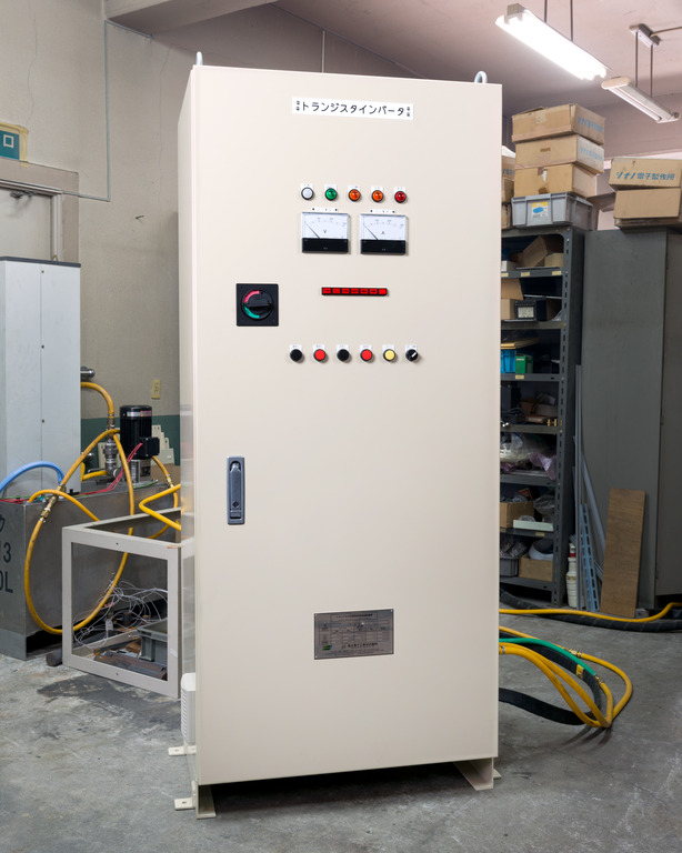
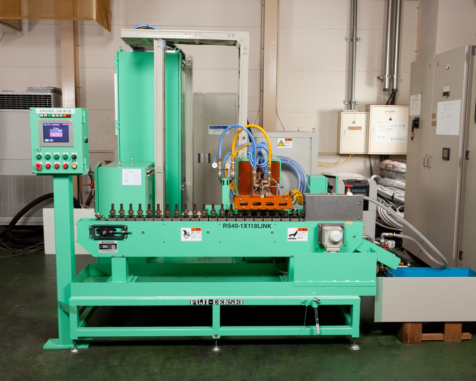
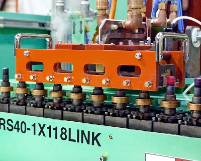
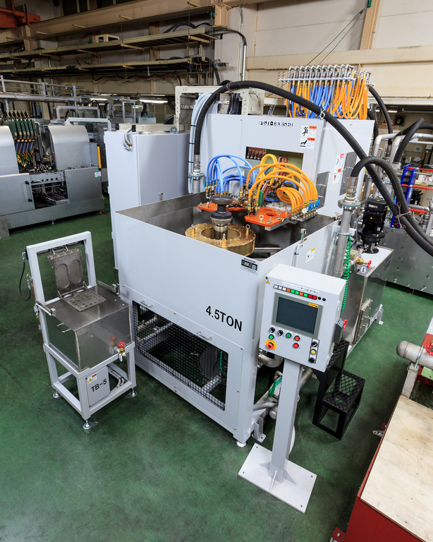
We manufacture induction heating machines and do job heat treatment.
This photo shows our originally developed induction heating converter FOCUS.
Manufactured entirely in-house from design to assembly,
we supply our customers with domestically made, guaranteed products.
Conversion efficiency is top class in the industry at 95%
and contributes to energy and cost savings.
~Induction Hardening Converter Development~

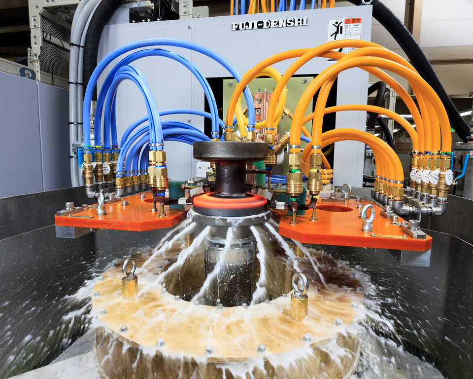
[Fuji Denshi Job Heat Treat Plant]
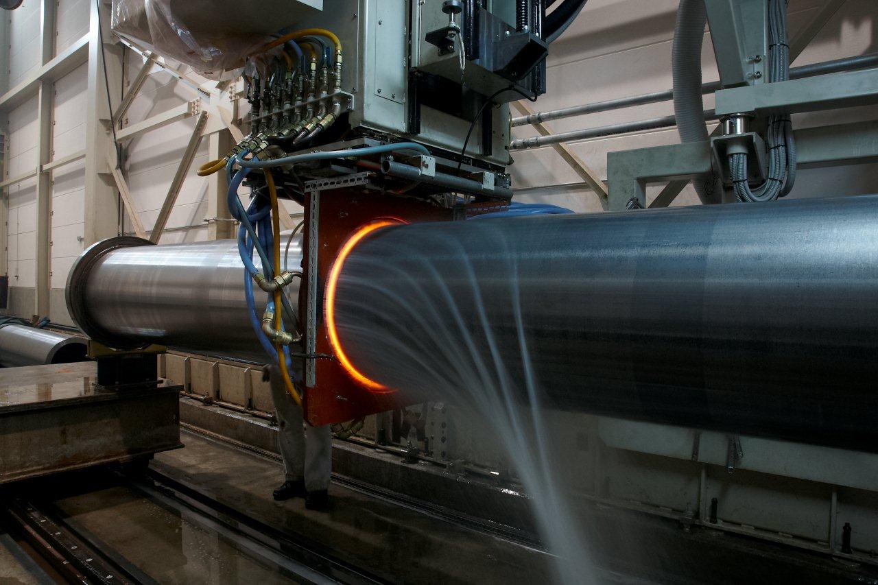
The large dip-quench hardening machine installed in our job heat treat plant
is mainly used for large gears and rollers.
It can treat parts up to 1.8m in diameter.
The photo shows the dip-spray process in action.

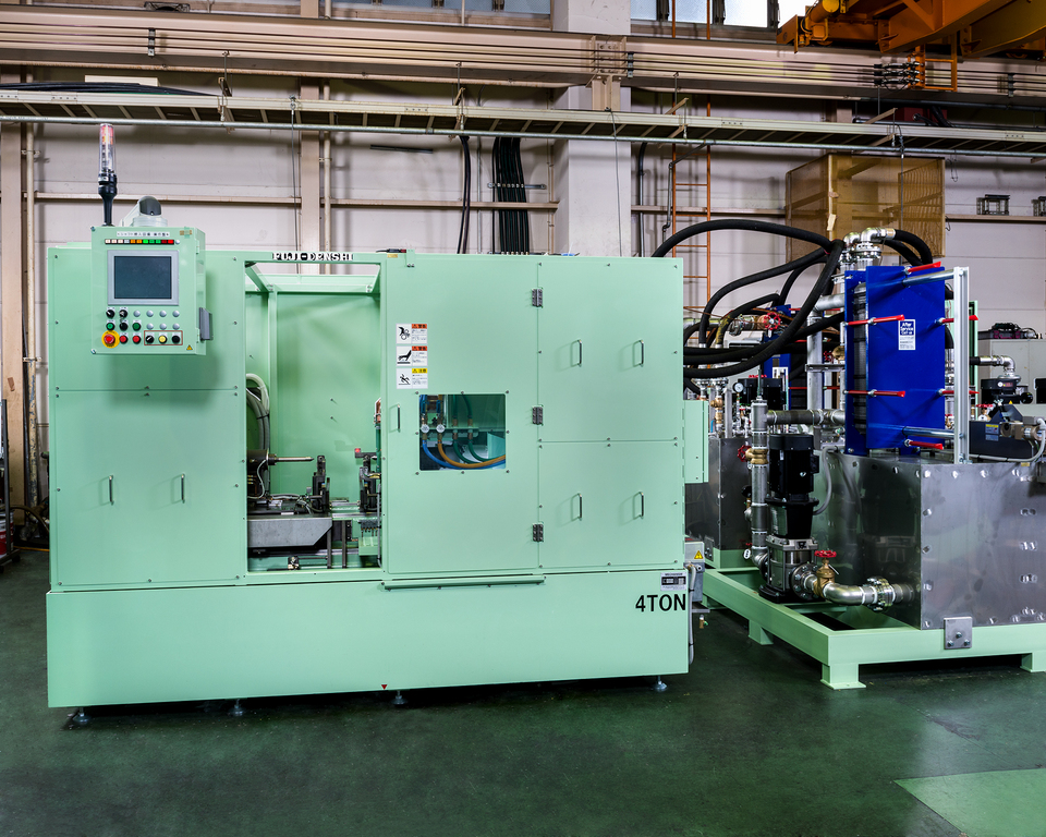
[Fuji Denshi Job Heat Treat Plant]
The small dip-quench hardening machine installed in our job heat treat plant
is mainly used for gears, rollers, and bearing races.
It can treat parts up to 0.65m in diameter.
Larger parts are treated with our large dip-quench hardening machine.
We recently introduced our originally developed compact transistorized converter, FIT.
FIT is suitable for low power applications such as hardening, heating, and brazing.
Continuing in the line of our FUJI-ELOMAT converter, the new FIT
is a less expensize option.
The high conversion efficiency results in at least a 55% decrease in power consumption
and 75% decrease in running cost compared to vacuum tube converters.
Our FIT converter is suited for various application including brazing.
We await your inquiry!
At Fuji Denshi, in addition to our specialized hardening and reheating processes,
we also perform post-processing.
Our shot blast machine is mainly used for shaft post-processing and can process
rod-shaped parts up to 780mm in length.
Leave your post-processing needs to us.
The photo shows the hardening station of a vertical scan induction hardening machine
for shafts used in motors, generators, and alternators.
This automatic machine can induction hardening various motor shafts from
automobile alternators to vessel generators.
Our vertical scan hardening machine can be designed to move not only the workpiece, but also the coil and power transformer unit.
With this design, we decreased the size of the hardening station and
the entire machine as well as made loading and unloading easier.
As a result, this machine performs high quality hardening while
decreasing operation time.
The photo shows our production machinery bed hardening machine during
automatic coil changing.
Our bed hardening machine's automatic coil changer reduces retooling time
and necessary work.
In the photo, the previous coil is returned to the coil station and the changer
picks up a new coil.
Our gate model bed scan hardening machine is the first machine in the world
to be installed with this device.
This large dip quench induction hardening machine is installed
in our job heat treat plant.
Outer ring hardening: up to 1800mm diamater, 350mm thickness
Inner ring hardening: up to 1500mm diameter, 150mm thickness
This machine performs one-shot hardening for large gears,
bearing races and more up to the above dimensions.
For gear hardening, this machine features
- even heating by ring coil
- even quenching by dip spray
to minimize runout and cracking.
By heating in two stages, preheating and main heating,
the case depth is deep even in the gear grooves.
Please contact us with your job heat treatment needs.

We manufacture bed induction hardening machines.
The pictured hardening machine is for industrial machine beds.
Our bed hardening machine features our automatic coil tracking system,
which maintains the gap between the coil and workpiece
by sensor during the automatic hardening process.
As seen in the photo, the extremely small gap between the coil
and workpiece is maintained throughout the process.
The power consumption by the workpiece is highly efficient,
while achieving an even casing, ensuring high quality and energy savings.
~Bed Hardening Machine Induction Hardening Machine
Industrial Machine Machine Tool Parts IH Heat Treat~

[Job Heat Treatment]
The photo shows our custom-made large dip quench hardening machine.
[Major workpiece types] bearing race, large internal gear, large gear
※ Outer diameter: up to Φ1800, thickness 350mm
※ Inner diameter: up to Φ1500, thickness 150mm
[Material] steel (S45C), stainless steel (SUS304), etc.
[One-Shot Hardening]
During scan hardening, the beginning and end points are heated
and quenched twice, which can cause cracking or soft spots.
In contrast, our one-shot hardening achieves a sufficiently deep casing
around the whole circumference of gears up to 1.8m diameter and 15 module.
[Dip Quench Hardening]
Immediately after heating, the workpiece is submerged in quenching water
and sprayed by quenching water jackets. This prevents the formation of
an air layer around the workpiece and ensures an even casing.
By controlling the water temperature and mixing speed,
the resultant casing can be controlled to high precision.
[Inner/Outer Simultaenous Heating]
The machine can be fitted with two power sources to heat the
inner and outer surfaces at the same time.
[Job Heat Treatment]
The photo shows the large parts hardening machine in our heat treatment plant.
The part size can be visualized by comparison with the workers
standing behind it.
This machine can treat parts up to 15m in length and 40 tons in weight,
which is the heaviest weight permitted to be carried on Japanese roadways.
Large parts treated with this machine include machine beds, columns,
and slide guides.
[Custom-made Machines]
The pictured machine is our horizontal scan induction hardening
and reheat machine for construction machinery shafts.
At Fuji Denshi, we refer to tempering as reheating to differentiate
from furnace methods.
The pictured machine is specified for front loading and unloading.
Loading is performed by robot and unloading is done automatically
by jigs and chute for a simple yet highly productive design.

The photo shows the hardening station of our all-purpose single axle
double bed vertical scan induction hardening machine.
Our vertical scan induction hardening machines typical move the coil
during scanning, but this machine was designed for the workpiece
to move as specified by our customer.
The machine also can perform one-shot hardening, as seen in the photo.
The coil heats the workpiece from above and the jacket quenches it from below.
By rotating the workpiece while heating with our line coil, the multi-diameter
workpiece is heating along the whole circumference.
The photo shows our vertical scan induction hardening machine for shafts
used in motors, generators, and alternators.
This machine can treat various shafts including for automboile alternators
and ship generators.
By setting parameters including output power, frequency, coil type,
workpiece size, feed speed, and quenching water flow,
our vertical scan hardening machine achieves high repeatability
As a result, runout is kept to a minimum for high quality hardening
and reduced operation time.

The photo shows our large part hardening machine in our heat treat plant.
This machine can treat parts up to 15m in length and 40t in weight.
The machine treat beds, columns, and slide guides, among other parts.
Our specialized technology for surface hardening controls quenching
to ensure minimum runout.
[Job Heat Treat]
The photo shows hardening of the teeth of a gear.
After heating, the workpiece is lowered into the quenching water,
where it is sprayed by additional quenching water to achieve an even casing.
We have a large-scale and small-scale dip-spray hardening machine
in our heat treat plant, which together can treat parts up to diameter 1.8m.
We have also manufactured and installed this same machine in our customer's plant.
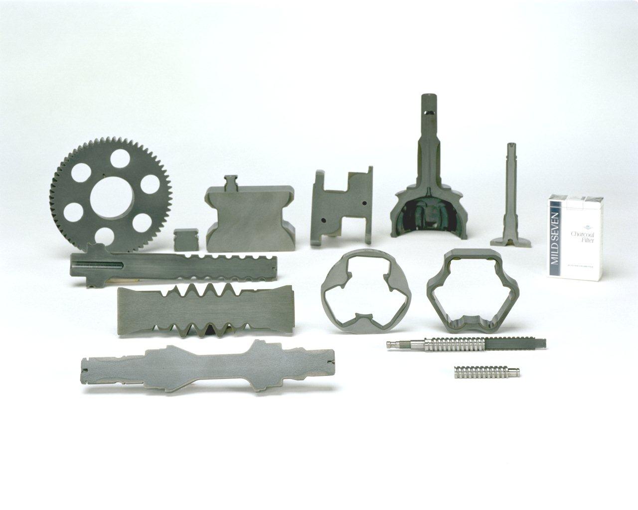
The photo shows cut samples of various machinery parts hardened
by our induction hardening machine.
The gray area of the cross section is the hardened casing.
As seen in comparison with the pictured cigarette box, the parts
are surprisingly small and the hardened areas are complexly shaped.
At Fuji Denshi, we apply our induction heating technology to meet
our customer's heat treat needs by supplying machines or providing
in-house job heat treat.
One of our specialties is heat treatment of large workpieces such as
construction machinery slewing bearing and machine tool beds and columns.
~Induction Hardening Cut Sample IH Heat Treat Automobile Parts
Production Machinery Parts~

[Large Bed Induction Hardening Machine:] 1100kW/10~100kHz
Maximum workpiece dimensions: W 3m x D 15m x H 2m
This hardening machine can treat workpieces up to 40t in weight
such as gears, crankshafts, columns, and beds.
By controlling the gap beween the coil and workpiece surface via sensor,
the coil automatically tracks the workpiece surface for stable hardening.
This is an original technology not available anywhere else in Japan.
Please consult us for hardening of any large parts.
The photo shows the hardening station of our horizontal hardening
and reheating machine for construction equipment shafts.
This machine automatically hardens mutiple types of shafts.
In the majority of our scan hardening machines, the workpiece is kept
stationary while the coil and power transformer unit moves,
a design technologically superior in general.
However, the shafts treated by this machine are relatively short.
To minimized cycle time, a horizontal scan design was chosen
with the focus on the loading/unloading speed of the shafts.
The workpiece is loaded horizontally by robot, then rolls along
the guide rail to the receive jig. After hardening, the workpiece
rolls along the unloading guide rail to the unloading station.

The photo shows a cut sample for a guide rail for linear accuators
hardened by our induction hardening machine.
The pattern seen on the cut sample shows that the shaft has been
hardened down to the bottom of the guide rail grooves.
The most difficult part of hardening this workpiece is preventing runout.
During scan hardening of the groove, the concave guide rail slightly twists.
Runout in the vertical or horizontal direction only can be corrected,
but twisting is not so easily corrected, which in general resultsin many
defective hardened parts and increased lead time.
Through extensive trial and error, we at Fuji Denshi developed
a combination of hardening machine, coils, and jigs to minimize runout.
We offer similar solutions for optimal hardening of a wide variety of workpieces.
Please contact us with your hardening needs.
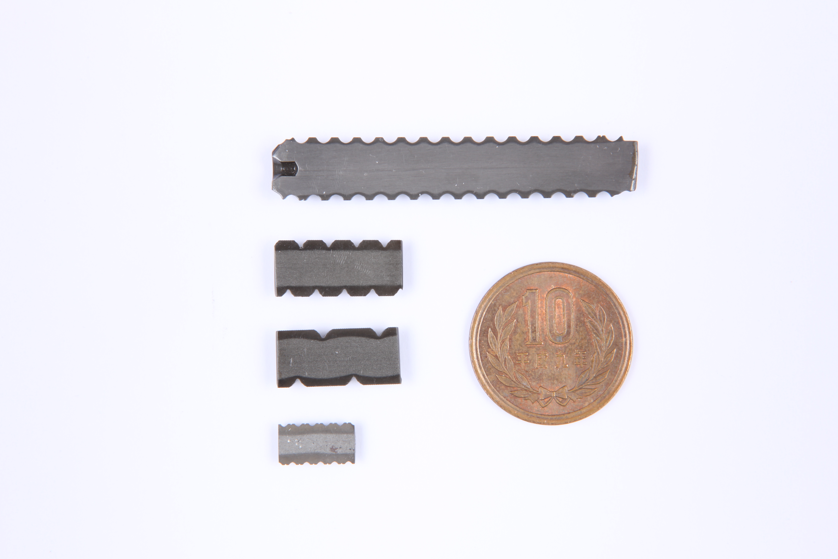
The photo shows a cut sample of a small diameter ball screw,
shown in comparison with a 10-yen coin.
Our method achieves an adequate case depth in the ball groove
without overheating even for small ball screws.
We design each coil custom-made and calibrate each machine
to meet our customer's specifications.
Please contact us with your induction heat treat needs.
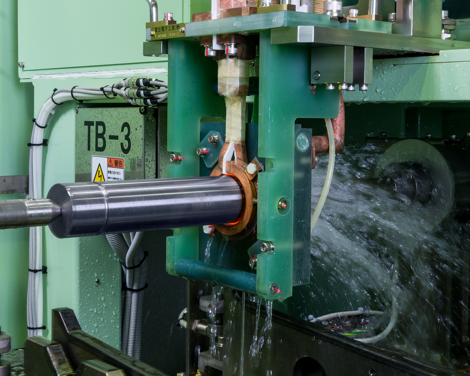
At our job heat treatment plant, we provide a wide variety of processes.
The photo shows a machine tool axle being hardened by our large vertical
scan hardening machine.
The gap between the workpiece and copper colored coil is extremely close.
If the coil gap is too large, the following quality defects can occur.
・For shafts, if the coil is off center, the hardened casing becomes uneven.
・Longer time required for heating increases the risk of overheating.
・The area surrounding the target area is also induction heated,
resulting in power loss.
To prevent these defects, we design coils with the optimal coil gap.
To prevent contact between the coil and workpiece, which can cause a
short circuit and damage the workpiece, the coils are moved to the required
distance from the workpiece before heating.
While time consuming, these check measures ensure the highest quality
hardening process in the industry.
~Induction Hardening Job Heat Treatment Coil Gap~
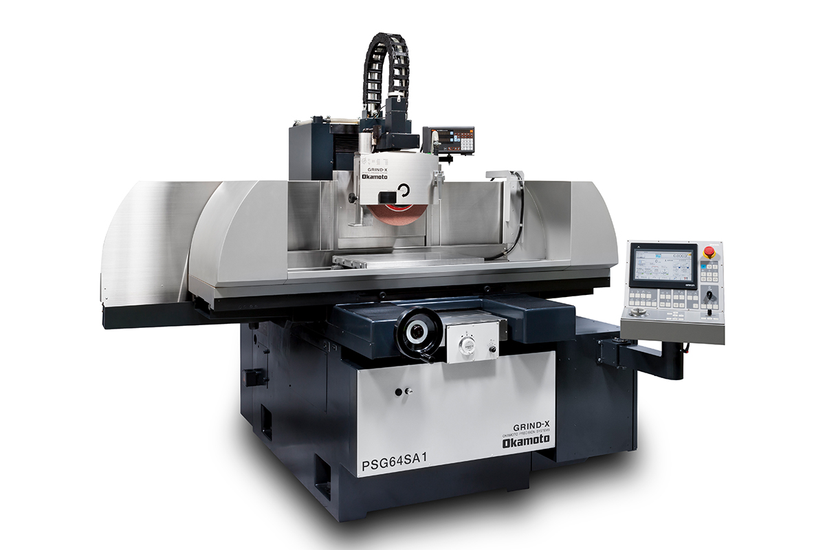
平面研削盤で国内市場シェアNO1を誇る岡本工作機械製作所のベストセラー平面研削盤PSG-SA1シリーズ。
小型から大型まで多彩なラインナップにより、ユーザーの工場専有面積に最適な研削盤をご提案いたします。
摺動面は工作機械伝統のV-Vキサゲ加工を行う事で高精度真直精度を実現。スピンドルには高剛性・メンテナンスフリーのアンギュラコンタクトベアリング方式を採用。
操作盤は大型カラータッチパネルを採用、自動研削サイクルを容易に入力可能。自己診断機能も搭載されており、長年使用しても安心して使える機能が搭載されています。
また自動化においては、標準で自動ドレス機能を搭載しており、加工ワークを取り外さずにドレスを行う事が可能な最新の汎用平面研削盤シリーズです。
【サイズラインナップ】
500×200mm
600×300mm
600×400mm
600×500mm
800×400mm
800×500mm
1000×500mm
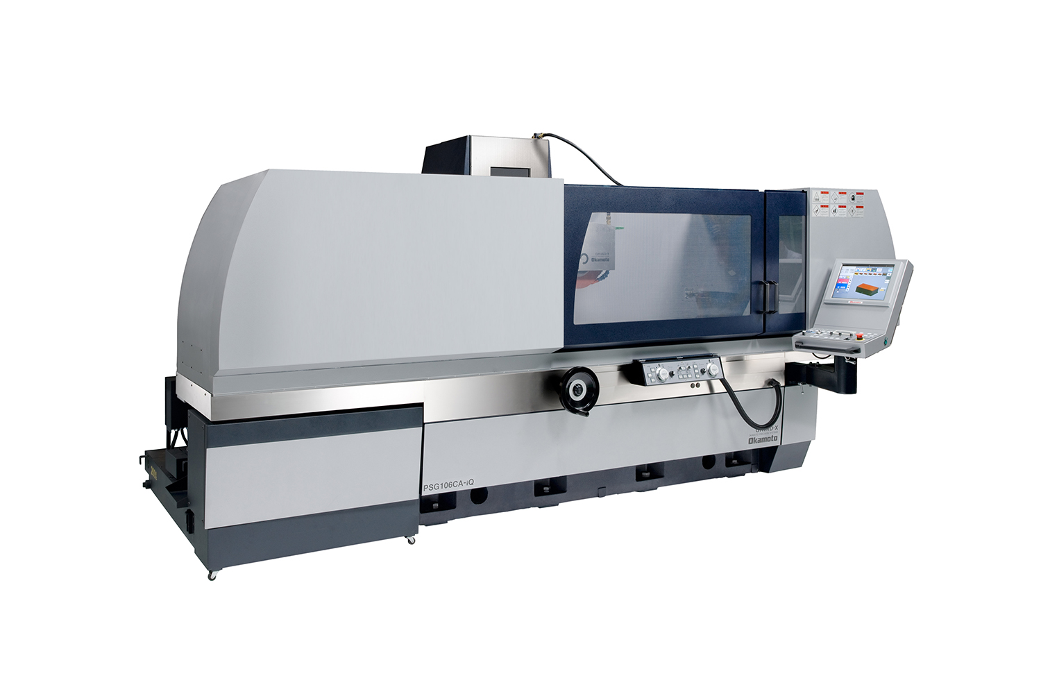
平面研削盤で国内市場シェアNO1を誇る岡本工作機械製作所のベストセラー平面研削盤PSG-CA-iQシリーズ。
小型から大型まで多彩なラインナップにより、ユーザーの工場専有面積に最適な研削盤をご提案いたします。
摺動面は工作機械伝統のV-Vキサゲ加工を行う事で高精度真直精度を実現。スピンドルには高剛性・メンテナンスフリーのアンギュラコンタクトベアリング方式を採用。高能率研削を実現するため、自社製の高剛性コラム構造を採用。切込み量を増やし、加工時間短縮によって生産性向上に大きく貢献します。
iQ操作盤は誰でもすぐに慣れることが出来る文字レスタッチパネルを採用。加工&ドレス&といし成形を1画面で設定が出来、研削盤を初めて使用するユーザーに最適なソフトです。
オプションにて更なる生産性向上を実現するファインバブル発生装置TWIN-BIXや高能率研削といしキュービトロンⅡといし等、お客様の目的に合わせた仕様をご用意しております。
【サイズラインナップ】
600×300mm
600×400mm
800×400mm
600×600mm
1000×600mm
1000×800mm
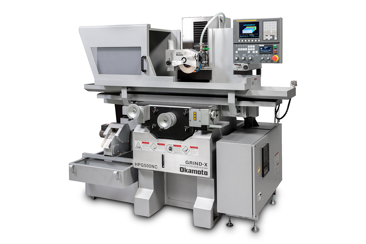
平面研削盤で国内市場シェアNO1を誇る岡本工作機械製作所のベストセラー小型成形研削盤HPGシリーズ。
小型タイプで左右ハンドルを選択。汎用作業とNC作業の両立を行うHPG500NCや金型パンチのカキアゲ研削を高速で行うHPG500NCS等、お客様の使い勝手とニーズに合わせたラインナップを用意しております。
オプションにて機上測定装置にも対応をし、研削盤の機上で定寸測定や形状確認を行う事も可能です。
【サイズラインナップ】
汎用タイプ HPG500
汎用左ハンドル HPG500L
NCタイプ HPG500NC
NC左ハンドル HPG500NCL
NC高速タイプ HPG500NCS
NC高速左ハンドル HPG500NCSL
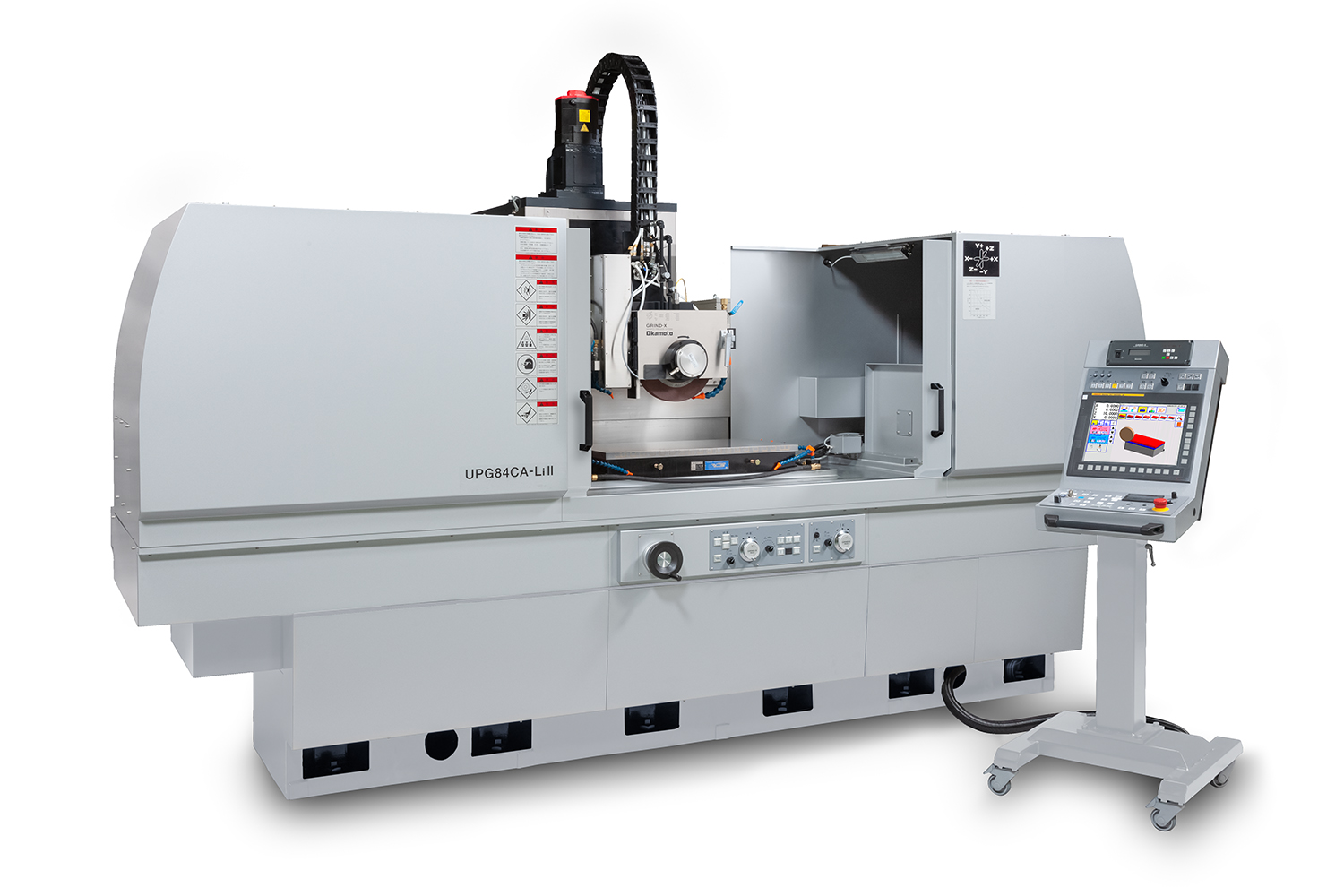
平面研削盤で国内市場シェアNO1を誇る岡本工作機械製作所のベストセラー平面研削盤UPG-CALiシリーズ。
中型から大型まで多彩なラインナップにより、ユーザーの工場専有面積に最適な研削盤をご提案いたします。
摺動面は最新の静圧スライド方式を採用、駆動方式にはリニアモータ駆動方式を採用する事で超精密の面品位・幾何公差をクリアする事が可能です。
スピンドルには回転精度抜群の静圧スピンドルを採用。鏡面研削や面ビレのない研削を容易に実現することが出来ます。
操作盤は誰でもすぐに慣れることが出来る文字レスタッチパネルを採用。加工&ドレス&といし成形を1画面で設定が出来、研削盤を初めて使用するユーザーに最適なソフトです。
オプションにて更なる生産性向上を実現するファインバブル発生装置TWIN-BIXや高能率研削といしキュービトロンⅡといし等、お客様の目的に合わせた仕様をご用意しております。
また自動化ではといしの動バランスを自動で調節するフルオートバランス装置、加工ワークの測定&補正研削を行う事が可能となる機上測定装置、全自動研削を実現する最新CAM等をご用意しております。
【サイズラインナップ】
600×300mm
800×400mm
1000×600mm
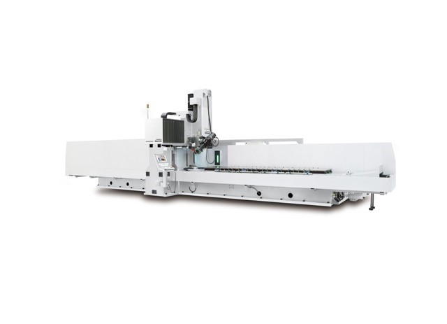
平面研削盤で国内市場シェアNO1を誇る岡本工作機械製作所のベストセラー平面研削盤UPG-CHLiシリーズ。
門型構造を採用しながら中型~大型まで多彩なラインナップにより、ユーザーの工場専有面積に最適な研削盤をご提案いたします。
摺動面は最新の静圧スライド方式を採用、駆動方式にはリニアモータ駆動方式を採用する事で超精密の面品位・幾何公差をクリアする事が可能です。
スピンドルには回転精度抜群の静圧スピンドルを採用。鏡面研削や面ビレのない研削を容易に実現することが出来ます。
操作盤は誰でもすぐに慣れることが出来る文字レスタッチパネルを採用。加工&ドレス&といし成形を1画面で設定が出来、研削盤を初めて使用するユーザーに最適なソフトです。
オプションにて更なる生産性向上を実現するファインバブル発生装置TWIN-BIXや高能率研削といしキュービトロンⅡといし等、お客様の目的に合わせた仕様をご用意しております。
また自動化ではといしの動バランスを自動で調節するフルオートバランス装置、加工ワークの測定&補正研削を行う事が可能となる機上測定装置、全自動研削を実現する最新CAM等をご用意しております。
【サイズラインナップ】
1500×800mm
2000×800mm
2000×1000mm
3000×800mm
3000×1000mm
4000×800mm
4000×1000mm
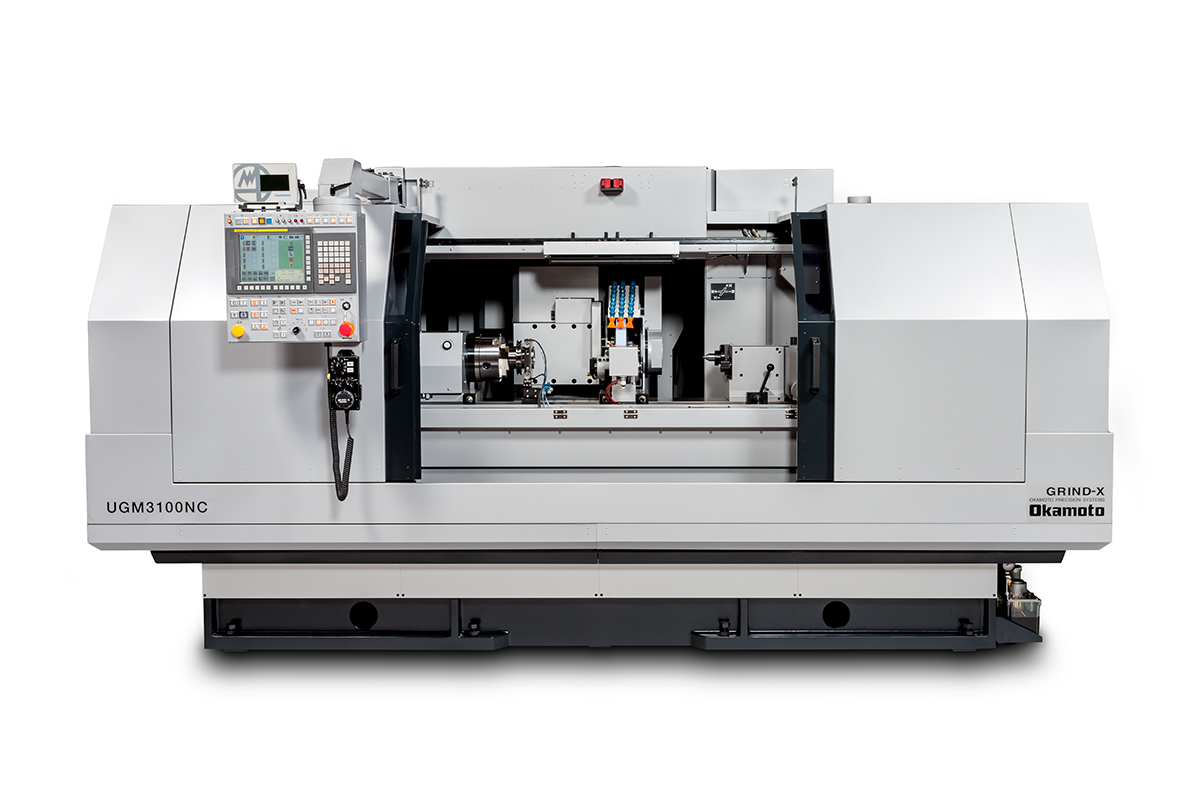
平面研削盤で国内市場シェアNO1を誇る岡本工作機械製作所が提案する円筒研削盤ベースの複合研削盤UGM-NCシリーズ。
円筒研削盤の構造をベースに採用、旋回といし軸により最大3つのといしまでを搭載可能。内外径の加工を行うユーザーの工場専有面積を削減するメリットがあります。
また内外径の加工を行うワークをワンチャッキングで加工するため、同軸度は高精度を実現することが可能です。また機内測定による自動化も対応をしています。
操作盤は誰でもすぐに慣れることが出来る文字レスタッチパネルを採用。加工&ドレス&といし成形を1画面で設定ができ、加工条件自動計算機能では加工ノウハウがないオペレータでも自動で加工条件を計算する機能が搭載されています。
【サイズラインナップ】
Φ300×600mm
Φ300×1000mm
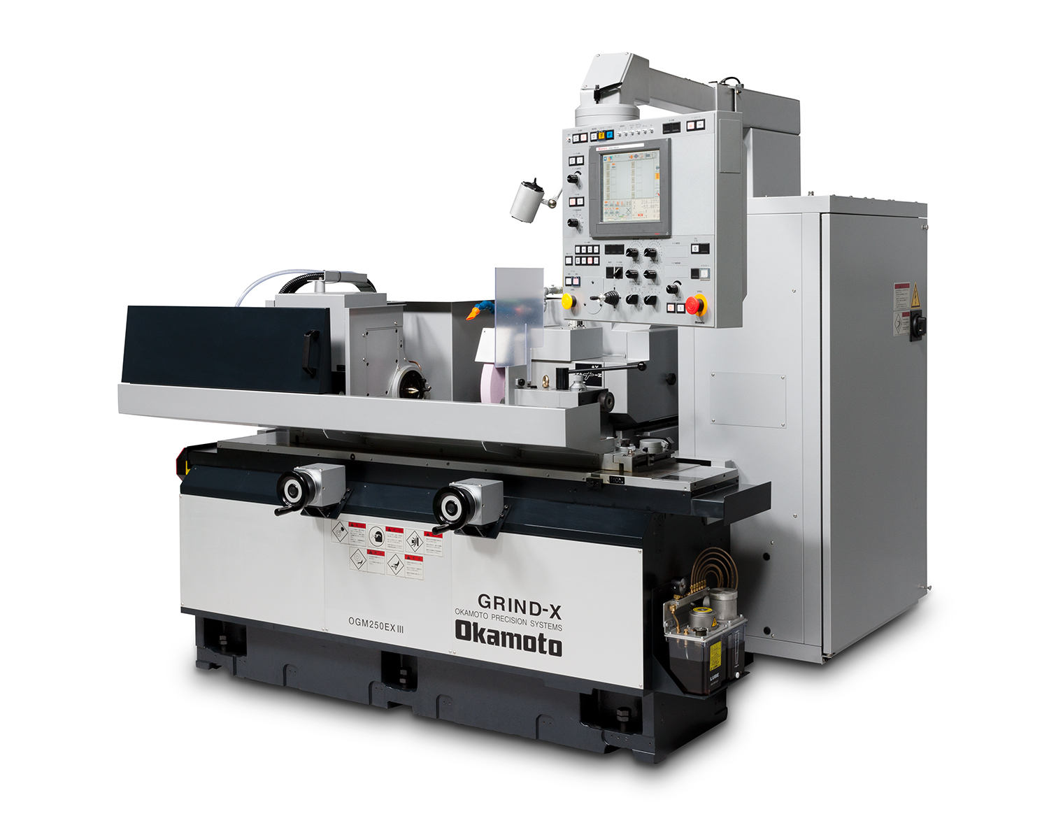
平面研削盤で国内市場シェアNO1を誇る岡本工作機械製作所が提案する円筒研削盤OGM-EXⅢシリーズ。
前側ハンドルによる汎用作業とNC操作盤による自動サイクルを両立可能な円筒研削盤。摺動面はV-V摺動面採用、油膜の浮上がり均一・スラスト方向に強い剛性を誇ります。またスピンドル方式にアンギュラコンタクトベアリングを採用することで剛性とメンテナンスフリーを実現、冷間鍛造金型パンチ・超硬・セラミックス類の高能率研削に最適な設計構造です。
操作盤は誰でもすぐに慣れることが出来る文字レスタッチパネルを採用。加工&ドレス&といし成形を1画面で設定ができ、加工条件自動計算機能では加工ノウハウがないオペレータでも自動で加工条件を計算する機能が搭載されています。
【プレーンタイプ】芯間×長さ
OGM225EXⅢ 200×250mm
OGM250EXⅢ 200×500mm
OGM330EXⅢ 300×300mm
OGM350EXⅢ 300×500mm
OGM390EXⅢ 300×900mm
OGM3150EXⅢ 300×1,500mm
[ユニバーサルタイプ]
OGM225UEXⅢ 200×250mm
OGM250UEXⅢ 200×500mm
OGM330UEXⅢ 300×300mm
OGM350UEXⅢ 300×500mm
OGM390EXⅢ 300×900mm
OGM3150EXⅢ 300×1,500mm
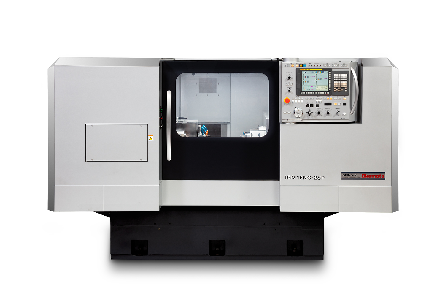
平面研削盤で国内市場シェアNO1を誇る岡本工作機械製作所が提案する内面研削盤IGM15NCⅢ-2B。
当社内面研削盤は汎用・NC・2軸NC・立型のラインナップを揃えており、新たに2軸NCの単軸駆動方式を採用したIGM15NCⅢ-2Bをラインナップ。内面研削盤でありながら大型といしを搭載した内外径の加工を実現します。
操作盤は誰でもすぐに慣れることが出来る文字レスタッチパネルを採用。加工&ドレス&といし成形を1画面で設定ができ、加工条件自動計算機能では加工ノウハウがないオペレータでも自動で加工条件を計算する機能が搭載されています。
オプションで機内測定や多関節ロボットによる自動ワーク搬送等にも対応。NCによるマクロプログラム作成でお困りのお客様には自動プログラミングソフトもご用意しております。

The Nisshin Sine Bar Chuck is a long-selling, best-selling tiltable chuck with a built-in sine bar, with nearly 30,000 units shipped to date.
Developed by our company—a precision press die manufacturer with over 60 years of history—this in-house product was originally created to dramatically streamline our own grinding process. We now offer it for sale to other metalworking and press processing companies.
We recommend using it in combination with small surface grinders from manufacturers such as Okamoto Machine Tool, Giken, Mitsui High-tec, Kuroda Seiko, and NIKKO.
For over 40 years since its release, each unit has been carefully handcrafted by skilled artisans using traditional methods. While this results in a higher price compared to competing products, it offers distinct advantages over later-developed similar sine bar chucks:
Precision and Durability:
The chuck uses a disc brake-like mechanism to secure the半月板 (half-moon plate) fixed to the spindle, ensuring a light clamping feel and precise spindle stopping. There is no loss of accuracy due to aging.
Enhanced Heat Dissipation
Unlike competing products that use simple resin-based fixes for the electromagnetic chuck electrodes, we use traditional soldering, which allows faster heat dissipation during machining.
Thanks to these overwhelming strengths, the Nisshin Sine Bar Chuck has earned a dedicated fan base among professionals who demand the highest precision and reliability.
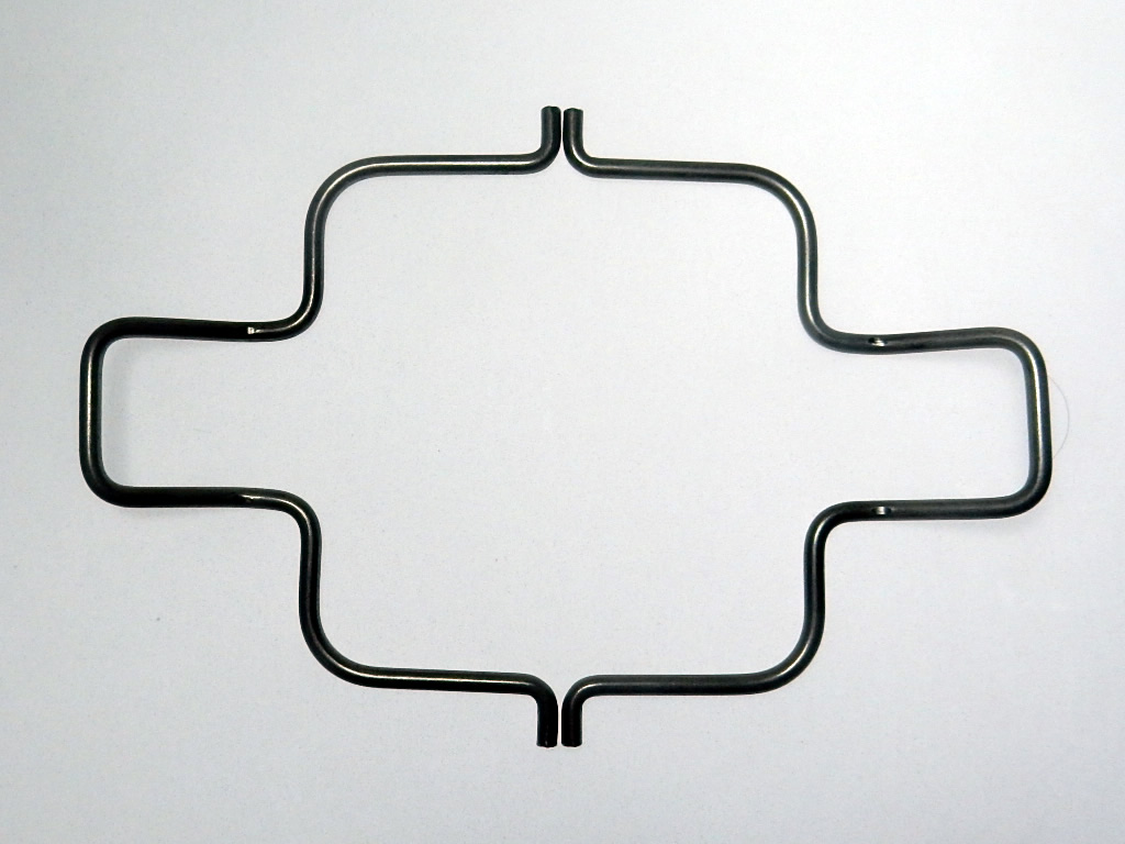
Wire springs are essential components for energy storage and vibration absorption in machinery, widely used in applications ranging from automotive to medical devices.
[Features]
• Versatile material compatibility: Stainless steels including SWC, 60C, and SUS304
• Advanced processing techniques: Bending and punching of wire and shaped materials
• Broad application range: From precision instrument parts to everyday items
• Flexible production: Capable of small-lot production for various product types
[Applications]
• Automotive parts
• Medical devices
• Electronic device terminals
• Industrial and agricultural machinery
• Precision instrument components
[Nippon Forming's Strengths]
• Micro-processing technology
• Expertise in complex shape manufacturing
• Comprehensive quality control
We specialize in manufacturing wire springs tailored to our customers' specific requirements. Our production process ensures consistent quality control from material selection through to final production.
We also specialize in precision processing of wire and strip materials, accommodating diameters from 0.1 to 5mm. Our NC-controlled manufacturing enables complex shape production.
For inquiries regarding wire springs or custom orders, please don't hesitate to contact us.
[Company Information]
Nippon Forming Co., Ltd.
Headquarter & Main Factory: 1-23-2 Kanamachi, Katsushika-ku, Tokyo
Tsukuba Factory: 2924 Ujikai, Ishioka-shi, Ibaraki
https://www.forming.jp/eng/
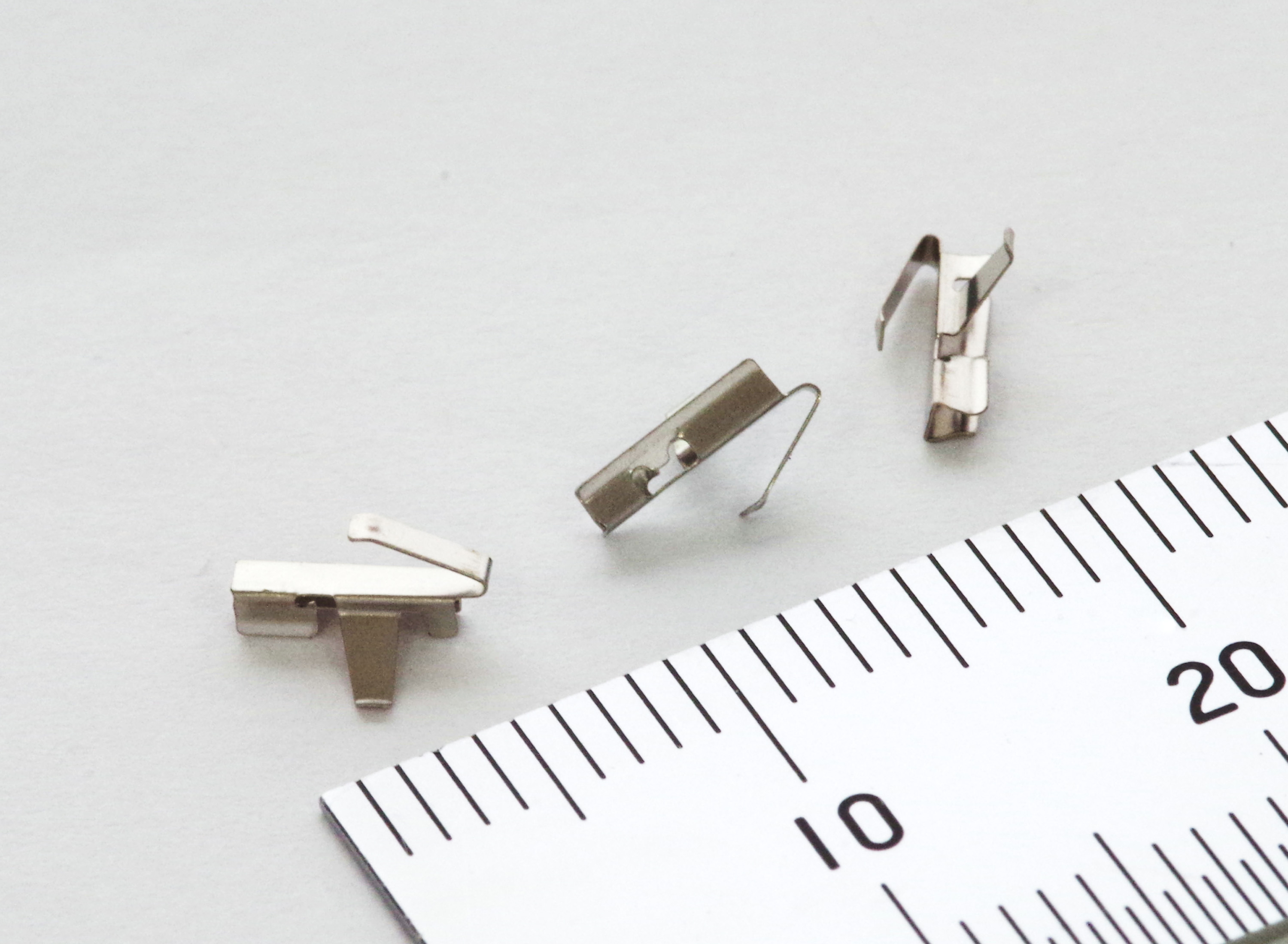
Material: SUS304CSP
Thickness: t0.15mm
Processing Method: Press processing using progressive dies
It is possible to incorporate various processing elements into a small shape.
This product is a leaf spring with two contact points in different directions within a compact space.
When considering parts for weight reduction, multifunctionality, etc., please provide details regarding space constraints and required functions. We can consider the shape and make proposals.
For more examples of leaf spring products, click here:
https://www.kyowa-hearts.com/spling/
☆ Frequently Asked Questions
https://www.kyowa-hearts.com/faq/
☆ Equipment Information
https://www.kyowa-hearts.com/setsubi/
☆ Contact & Process from Prototyping to Mass Production
https://www.kyowa-hearts.com/flow/
<Contact Information>
Kyowa Hearts Co., Ltd. – Rumi Sakamoto
■ Address: 1-5-1 Takata-Nishi, Kohoku-ku, Yokohama, Kanagawa, Japan
■ TEL: 045-593-6116 FAX: 045-593-6121
■ Official Website: https://www.kyowa-hearts.com
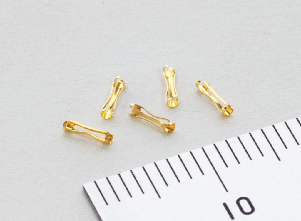
【Product Specifications】
Product Name: Leaf Spring for Socket Contact
Material: C5210R-H (Phosphor Bronze)
Thickness: t0.1
Total Length: 4
Inner Diameter:
Both Outer Sides: φ1.3mm
Center Section: φ0.8mm
Slit Dimensions: Width 0.3 × 6 slots
Roundness Accuracy: Within 0.05
Processing Method: Progressive Curling Processing
Key Explanation
Curling processing refers to the technique of rolling a flat sheet into a cylindrical shape.
The product shown in the image is a tsuzumi (drum) shape, where the center diameter in the length direction is larger than the diameters at both ends. Additionally, it is also possible to process a tawara (barrel) shape, which has a similar structure.
We can handle various spring materials, including phosphor bronze, beryllium copper, and stainless steel (SUS).
We have also successfully developed even smaller-sized components.
For more examples of leaf spring products, click here:
https://www.kyowa-hearts.com/spling/
☆ Frequently Asked Questions
https://www.kyowa-hearts.com/faq/
☆ Equipment Information
https://www.kyowa-hearts.com/setsubi/
☆ Contact & Process from Prototyping to Mass Production
https://www.kyowa-hearts.com/flow/
<Contact Information>
Kyowa Hearts Co., Ltd. – Rumi Sakamoto
■ Address: 1-5-1 Takata-Nishi, Kohoku-ku, Yokohama, Kanagawa, Japan
■ TEL: 045-593-6116 FAX: 045-593-6121
■ Official Website: https://www.kyowa-hearts.com
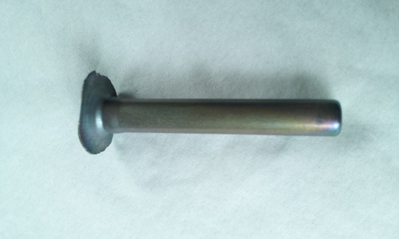
The photo shows deep drawing of pure titanium type 1, Φ6.3 × 40.
We also have experience processing the same shape using beta-type titanium alloy.
This is a deep-drawn product formed through multiple press processes from sheet material, with punching on the side and top surfaces.
It is manufactured using a press method with a die.
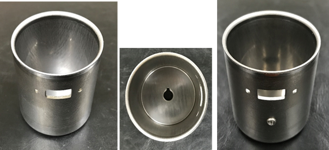
Material: SUS304
Base plate thickness: t1.0
Application: Solenoid valve
Dimensions: φ24 × 35mm
Tolerances:
Flatness: ±0.03μm
Perpendicularity: ±0.03μm
Step at the opening, R0.1
Burr: ±0.04μm
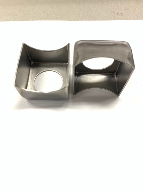
This is a square deep-drawn product formed through multiple press processes from sheet material, with punching on the side and top surfaces.
It is manufactured using a press method with a die.
Material: SUS304
Base plate thickness: t0.5
Application: Solenoid valve
Dimensions: 30mm × 30mm × 20mm
Tolerances:
Flatness: ±0.1μm
Radius: R0.5
Burr: ±0.03μm
This is a deep-drawn product formed through multiple press processes from sheet material.
It is manufactured using a press method with a die.
Material: SUS304
Base plate thickness: t0.8
Application: Solenoid valve
Dimensions: φ23 × φ16 × 35mm
Tolerances:
Roundness, concentricity, parallelism: ±0.03μm
Perpendicularity: ±0.03μm
Step at the opening, opening radius: R0.5
Burr: ±0.02μm
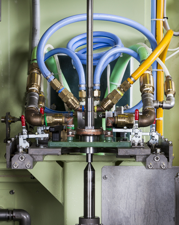
The photo shows the hardening station of a reduction gear hold flange
induction hardening and reheating machine, seen from above.
The outer circumference of the disc-shaped workpiece in the center
is heated by the ring coil.
The workpiece is loaded/unloaded from under the coil.
After the workpiece is set, the jig raises the workpiece into the coil,
where it is heated at a very close distance.
After heating, the jig carries the workpiece down to the quenching position.
Quenching water is sprayed from the surrounding jackets
for quick and even quenching.
This machine is designed to achieve high hardening quality
by optimizing heating time, power, quenching time, and water flow.
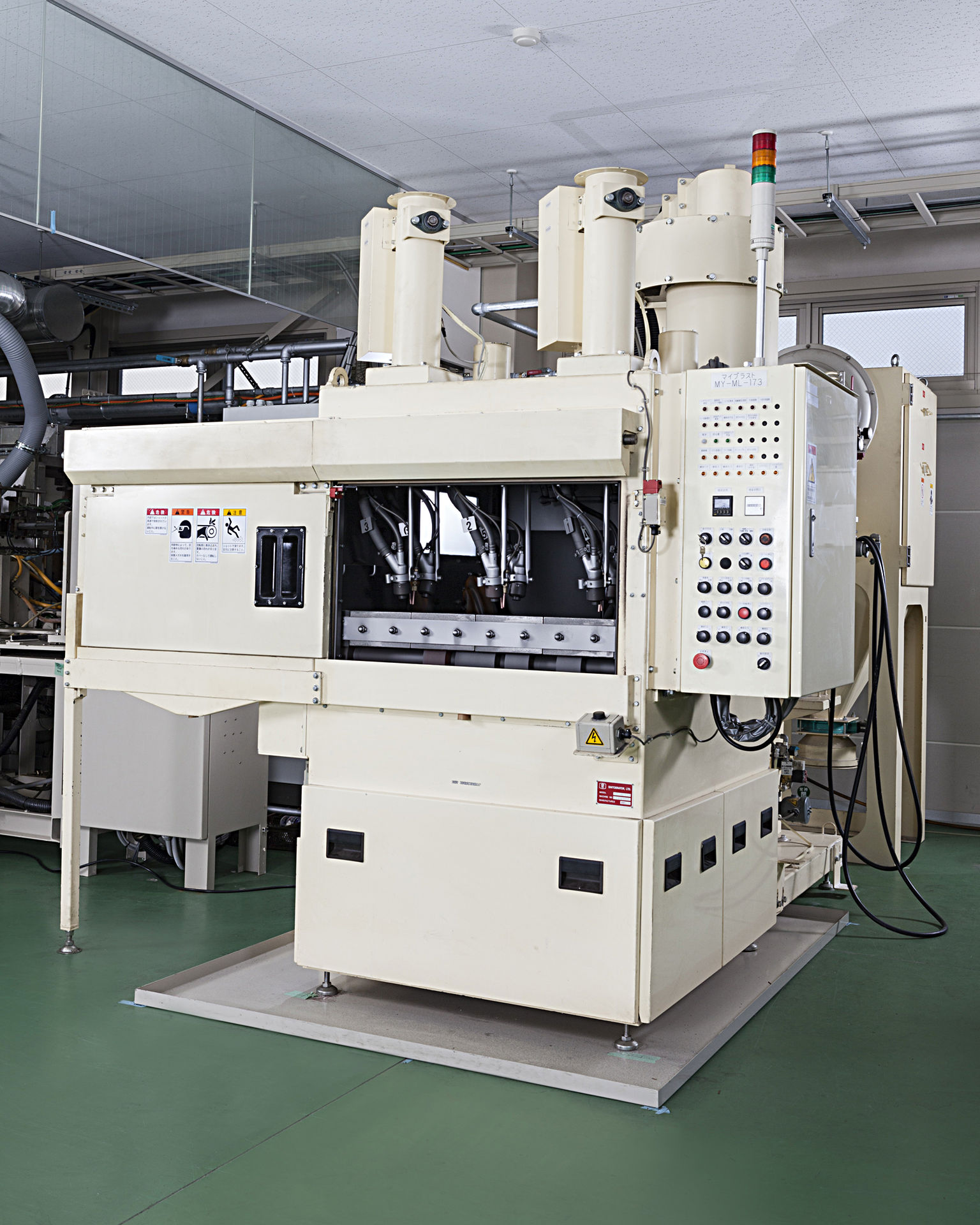
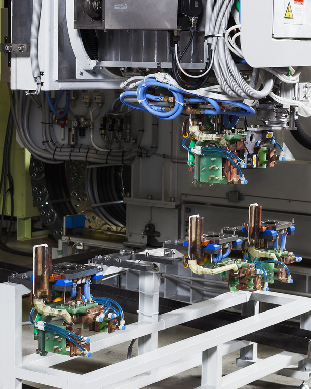
The photo shows a reduction gear hold flange induction hardening
and reheating machine.
With one converter supplying power to three hardening machines,
this system is able to harden and reheat flanges of different specifications
in parallel.
※At Fuji Denshi, we refer to tempering as reheating to differentiate
from furnace methods.
A robot loads the workpiece from the front port.
Each machine is operated under separate settings to achieve
high productivity and quality.
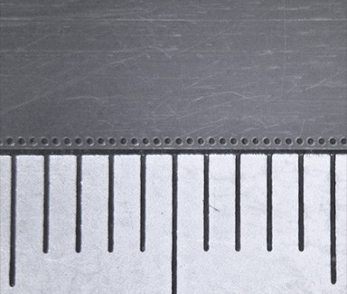
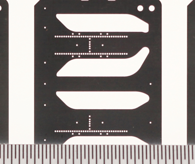
The photo shows a precision micro-hole press component manufactured for the automated equipment industry.
Using progressive press processing, we punch φ0.05 micro-holes at a position 0.10 mm from the edge of laminated film material with a thickness of 0.03 mm, demonstrating high-precision edge processing capability.
Material: Laminated film
Based on our expertise in the design and manufacture of press dies and engineering plastic molds, we provide fully integrated, in-house production from terminal press processing to insert molding within a single facility.
IATF 16949 Certified
The same rigorous quality management standards applied to automotive components are also implemented across all non-automotive products.
For stable, high-volume production of precision micro-hole press components for the information and automated equipment industries, trust your requirements to us.
~ Technology is Beautiful ~ Shinshu Yoshino Electric Co., Ltd.
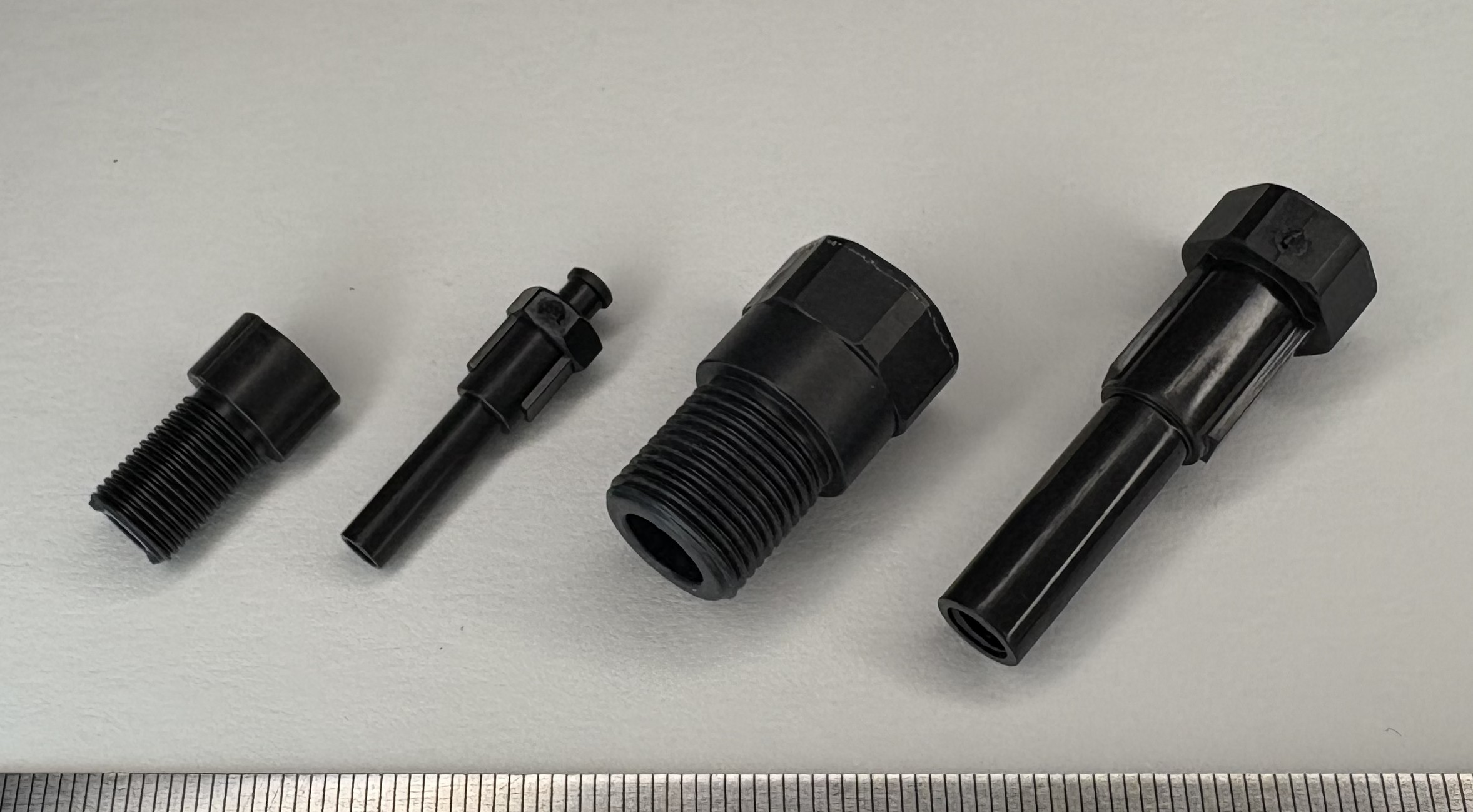
The photo shows a resin-made hexagonal screw component.
Designed for weight reduction, this part is molded from CFRTP as a metal replacement solution. In addition to external threads, internal threads are also formed by molding using a core mechanism, enabling complex thread geometries in a single process.
At Shinshu Yoshino Electric, we have developed a proprietary composite molding technology known as the Direct Fiber Feeding Injection Molding Method. By modifying the injection molding machine, continuous fibers are fed directly into the process, enabling the production of high-performance CFRTP components.
Material
Resin: PA-based resin
Reinforcement: Carbon fiber
Based on our expertise in the design and manufacture of press dies and engineering plastic molds, we provide fully integrated, in-house production—from terminal press processing to insert molding—within a single facility.
IATF 16949 Certified
The same rigorous quality management standards applied to automotive components are also implemented across all non-automotive products.
For stable, high-volume production of lightweight, high-strength resin fasteners and precision components, trust your requirements to us.
~ Technology is Beautiful ~ Shinshu Yoshino Electric Co., Ltd.
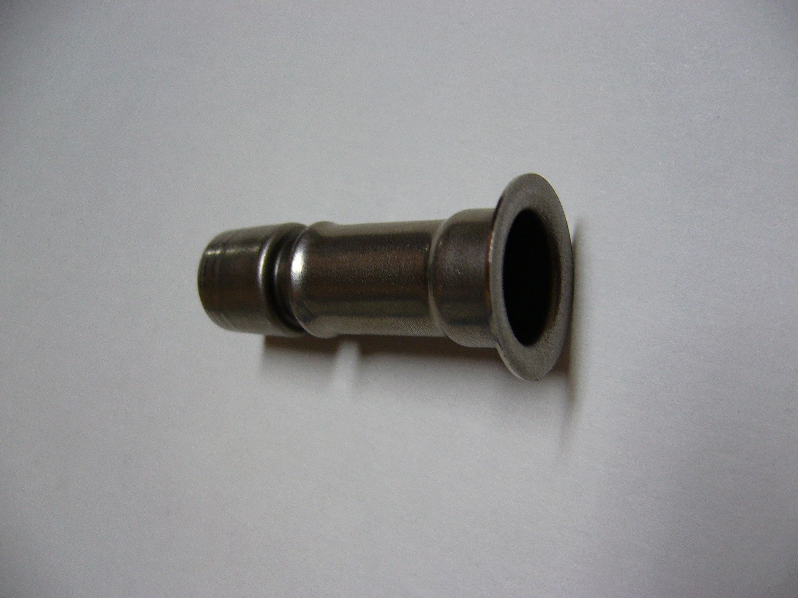
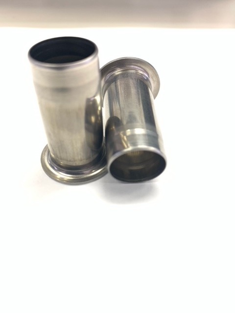
This is a component that was traditionally manufactured through machine processing but has now been converted to press processing using stainless steel deep drawing.
A notable achievement is the successful creation of an O-ring groove.
Approximate dimensions: Total length 37mm, φ12.5mm, flange φ19mm
O-ring groove: φ9.2mm, width 2.3mm.
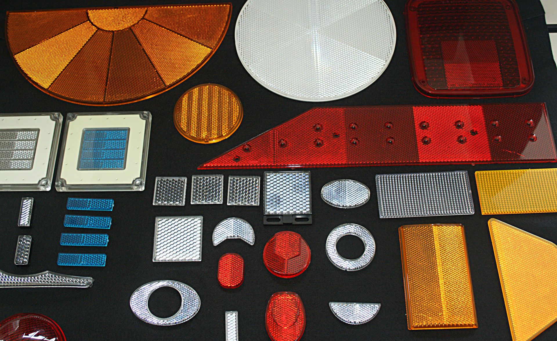
The production of reflex reflectors—especially for photoelectric switch sensors and bicycles—requires advanced design, machining, and assembly techniques. Only a select few companies worldwide possess the expertise to manufacture such precision molds.
Since 1958, when we successfully developed reflector molds using our proprietary technology, we have been supplying molds, standard electroformed products, and molded components to major brand companies both domestically and internationally.

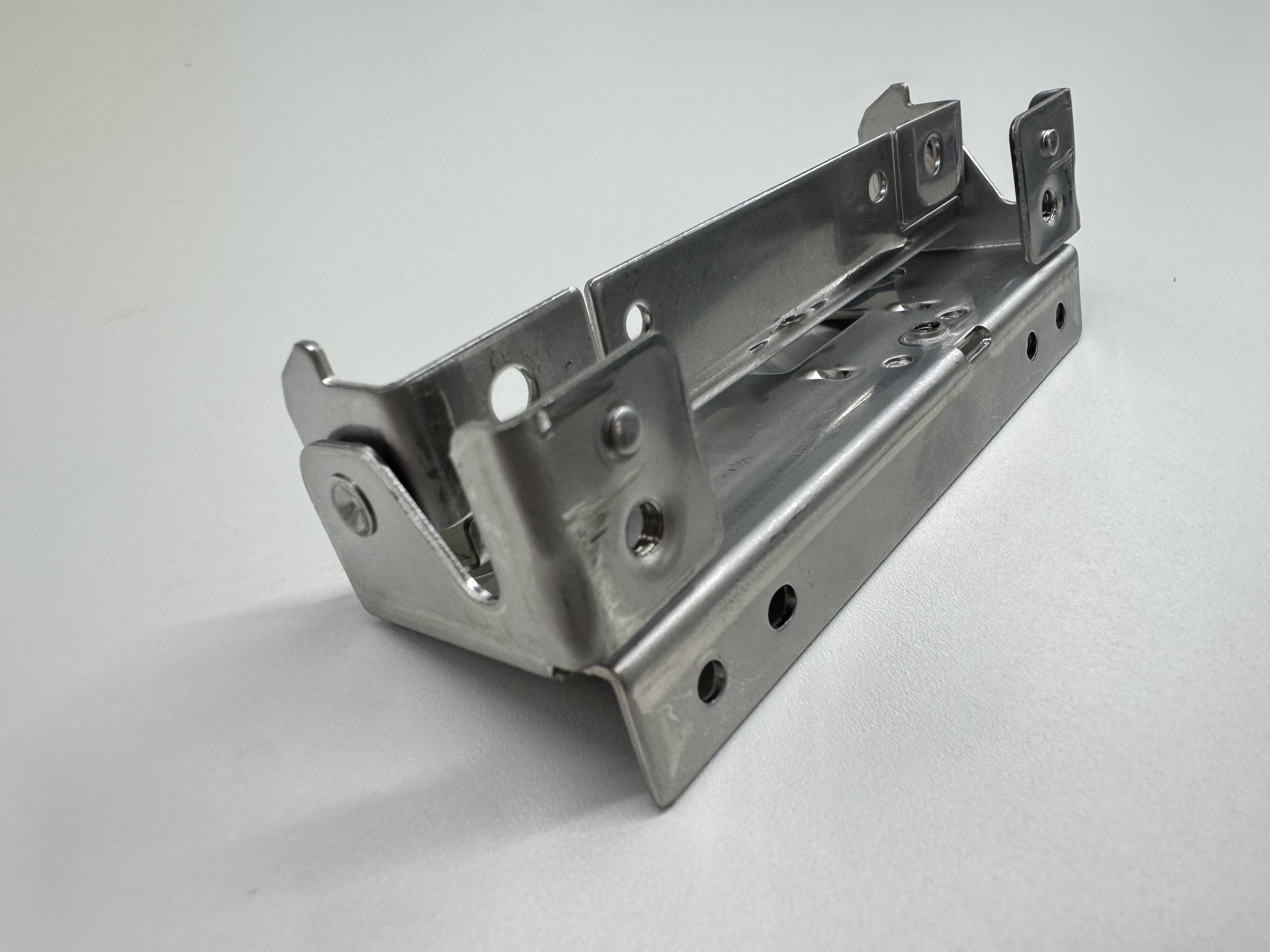
[Current State of Safety Components in the Automotive Industry]
In recent years, with the advancement of automotive safety performance, the placement of airbag systems has become increasingly diverse. Among these, inflator brackets have gained attention as critical functional components that reliably support the deployment force of airbags. These parts are designed to install tanks in small spaces, requiring precise design and manufacturing to deliver maximum performance within limited areas.
[Technical Challenges in Inflator Bracket Manufacturing]
When manufacturing primarily with mild steel sheets, the following technical challenges arise:
Strength design to withstand the impact of airbag deployment
Achieving optimal shapes within limited spaces
Controlling thermal deformation during welding
Ensuring quality stability during mass production
Achieving fine dimensional accuracy
[Solutions in Prototype Development]
► Problem Solving with Advanced Design Systems
Accurate representation of complex shapes using 3D design with CATIA
Pre-verification of issues through press forming simulation with JSTAMP/NV
Reducing rework by optimizing designs at the development stage
► Quality Assurance with High-Precision Processing Technology
Press forming using high-quality molds
Precision machining with 3D 5-axis laser cutting machines
Welding and assembly with diverse welding equipment
Fine adjustments achieved through skilled craftsmanship
► Establishment of Quality Assurance Systems
Full inspection using coordinate measuring machines (CMMs)
Operation of a quality management system based on ISO 9001
Ensuring reliability through non-destructive testing of welded joints
[Implementation Results and Achievements]
✔ Tangible Benefits Experienced by Customers
1. Reduced Development Time
Shorter lead times from design to production
Improved development efficiency through early issue detection
2. Stabilized Quality
Achieved defect rates of less than 0.1%
High-precision machining with dimensional accuracy of ±0.2mm
Minimized post-welding deformation
3. Cost Optimization
Cost reduction proposals during the design phase
Competitive pricing through efficient production systems
Reduced additional costs by minimizing rework
[Future Outlook and Technological Development]
With the electrification and lightweighting of automobiles, new demands are emerging for inflator brackets. To meet the high-performance requirements and diverse placement of airbags, our company is advancing further technological innovations through the following initiatives:
Enhanced compatibility with high-strength materials
Introduction of automation technologies
Utilization of digital twins
[Inquiries and Request for Materials]
We have prepared more detailed technical materials.
★ Download materials here
https://ja.nc-net.jp/company/22325/dl/catalog/207206
For technical consultations, feel free to contact us:
https://ja.nc-net.jp/company/22325/inquiry/
[Company Overview]
Timec Co., Ltd.
Address: 197-1 Nishigori, Soja City, Okayama Prefecture 719-1164, Japan
TEL: 0866-93-1269
FAX: 0866-93-2540
Corporate Website: https://timec.co.jp/
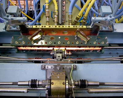
We have achieved to establish simultaneously and automatic cam quenching which can manufacture 240/h and 3600 sections resulting in overall cost reduction.
For those work which each cam and journal are placed side by side, by using our uniquely produced outlet ring, the ring will insulate any effect towards unnecessary parts.
Also, by adjusting bearing and cam, other types and shapes of camshaft can be processed.
We will gladly support prototyping, quality inspection, equipment installation, and maintenance of equipments after installation.
*Please consider us for prototyping, manufacturing by commissioning, and buying equipments.
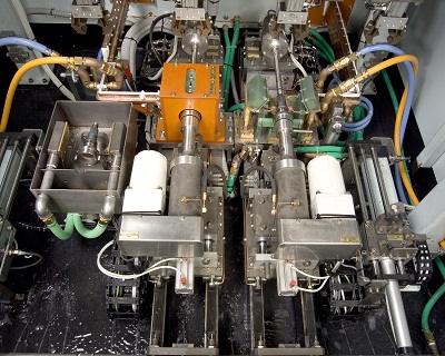
Picture:Double Quenching. Cycle time 1:27 per 2.
Hands on and off model.
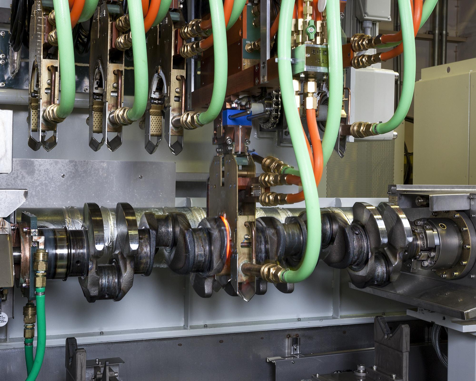
【Crankshaft Quenching Machine】
When quenching pins and journals of crankshaft simultaneously, miniaturizing transformers (disk transformer) or quenching towards the same direction as turning pins allows formation of a quenching layer along a pin diameter.
“Power reduction method,” top and bottom uniformed quenching technique by reducing the output on the pin top for R-quenching, can minimize the possibility of distortion.
The above quenching technique can be in-line and for such case, we will gladly design to match the customer’s request.
Please feel free to contact us.

At Fuji Denshi, we design, manufacture, and sell induction heating machines
as well as do job heat treatment and prototype development.
The photo shows our stub shaft axle hardening and reheating machine.
The one-shot hardening method using our line coil achieves an ideal case
pattern even with the varying diameter of the workpiece, while saving energy.
The entire length of the workpiece is quenched simultaneously,
ensuring the residual heat over the part's length is even and
preventing cracking and uneven case hardness and depth.
(Even heating / Even quenching)
Heating and quenching are both even over the entire surface,
so runout is kept at a minimum even without the need for a straightening roller.
The residual stress along the axle axis contribues to large increases
in the part's durability and strength.
(2x by comparison)
Scan hardening can easily cause uneven hardness and low axial strength.
Our one-shot hardening requires only half the power of scan hardening to better results.
This is an induction annealing machine for studs, a type of shaft jig
for cam followers.
After hardening the entire surface by carburizing, only the screw section
is annealed by induction.
As seen in the photo, the workpiece is loaded manually from the left
and carried by conveyor to the annealing station.
Annealing is done by continuously heating the workpiece as it passes
through a tunnel coil.
Then it is quenched at the after quenching station and automatically
unloaded by conveyor.
The machine was developed to replace the older model that used
vacuum tube converters and turntables.
We continue to develop machines with high productivity using
the simplest possible design.
Please contact our sales department with your needs.
This is an induction annealing machine for studs,
a type of shaft jig for cam followers.
After hardening the entire surface by carburizing, only the screw section
is annealed by induction.
As seen in the photo, the workpiece is carried from the left by conveyor
through the tunnel coil, where it is continuously heated,and out to the right.
This machine can be equipped with 3 types of coils and 2 types of jigs
to treat 11 different workpieces.
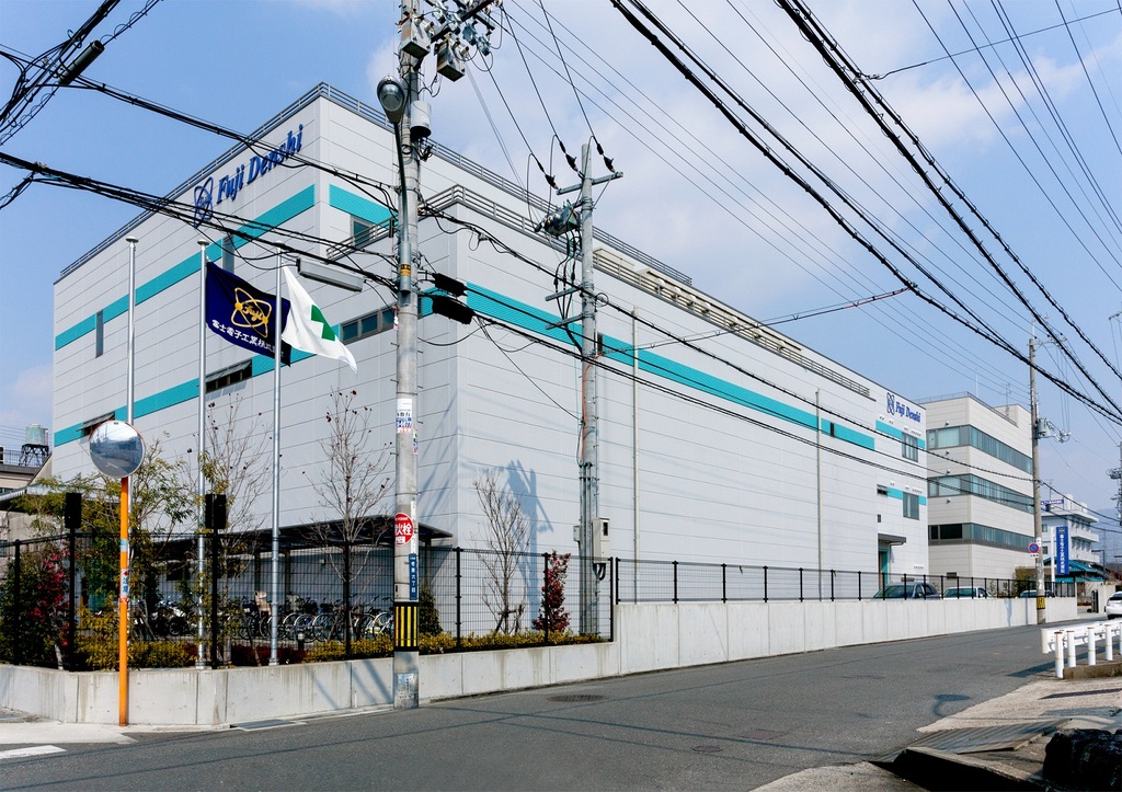
At Fuji Denshi, we manufacture high frequency induction heating machines.
We also have a heat treat plant at our headquarters In Yao, Osaka.
While we consider induction hardening our specialty,
we have also developed many technologies in other fields.
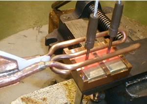
The photo shows brazing by induction. Compared to brazing by gas burner,
induction is more energy efficient and has higher repeatability.
We have supplied this induction solution to blade and tool manufacturers.
For customers considerig brazing solutions, feel free to contact us.
~High Frequency Induction Heating Brazing IH Brazing Heat Treat~
We specialize in precision micro-hole components for the low-voltage, home appliance, and office automation (OA) equipment industries.
Using stainless steel (SUS) and specialized resin films, we perform precision press processing to create fine holes.
Specifications:
Hole Diameter: φ0.100mm
Pitch: 0.15mm
Process Flow:
Press mold design & manufacturing → Press component processing
Product Details:
Size: 30mm × 40mm
Production Volume: 5,000 units/day
Production Lead Time: 1–2 months
Additionally, we manufacture a wide range of products, including those for the automotive industry.
For micro-hole press processing, please contact Shinshu Yoshino Electric.
Lần này, chúng tôi xin giới thiệu sản phẩm bản lề Hinji.
★ Bản lề Hinji là gì?
Là chi tiết dùng để liên kết và đỡ cửa hoặc nắp, giúp chúng có thể đóng mở linh hoạt.
Tên gọi khác: Bản lề Chouban
Tại Hanno Seimitsu Kogyo, thành viên của Tập đoàn Shinei Holdings – chúng tôi chuyên sản xuất bản lề bằng thép không gỉ (SUS) với công nghệ dập liên hoàn.
★ Điểm nổi bật ★
Có thể gia công đồng bộ từ dập đến dập ghép lắp ráp hoàn thiện (ASSY) trong cùng một quy trình.
Nhờ áp dụng khuôn dập liên hoàn, sản phẩm được chuyển tiếp tự động giữa các công đoạn mà không cần thao tác di chuyển thủ công, giúp nâng cao hiệu suất sản xuất và đảm bảo độ ổn định chất lượng.
Nếu Quý khách cần gia công bản lề bằng phương pháp dập liên hoàn với quy trình sản xuất khép kín, vui lòng liên hệ với chúng tôi.
______________
Hanno Seimitsu Kogyo Co., Ltd.
〒357-0013, 783-8 Ashikariba, Hanno-shi, Saitama-ken, Japan
TEL: +81-42-973-1251
FAX: +81-42-973-6924
HP: https://www.hns.co.jp
Người phụ trách: Ông Oda
______________
-464
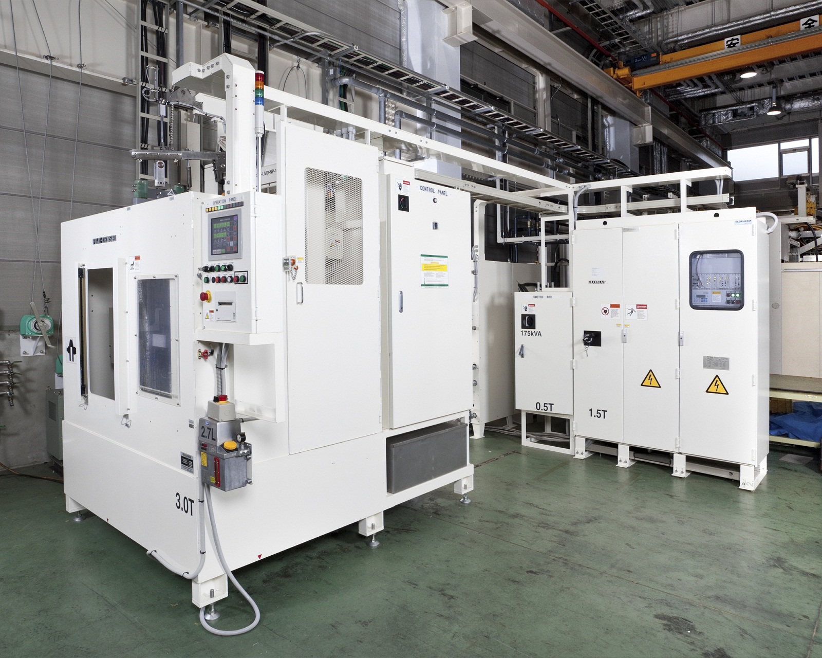
【Ordered Equipment】Drive Shaft Induction Quenching Equipment
[Future]
①A single unit production 225 per an hour.
②Compared to a movable induction quenching machine, a single shot system is 40 ~ 50% energy savings.
③40% better diameter ratio of induction quenching depth, resulting in improved fatigue strength.
④Less than 1/1000 of max length bending and low distortion treatment is applicable.
IT
[Cutting Edge IH Hardening Technology]
Since our founding, Fuji Denshi has continued to develop cutting-edge
induction hardening technologies.
Today, as a leading company in precision hardening technology,
we provide state-of-the-art technologies for our customers' needs.
◆ IH Job Heat Treating
With our technological knowledge and speed, we provide quality processing
for even complicated and large-sized parts.
◆ IH Heat Treat Machine Manufacturing
We design and manufacture machines implemented with the most suitable
hardening method to meet our customer's specifications, reuqests, and
production environment.
~Hardening Induction Job Heat Treatment Machine~
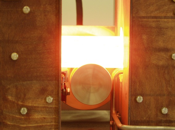
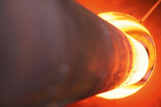
The photo shows heating of a billet for a forging process.
In addition to induction hardening machines, Fuji Denshi also features
forging billet heaters, melting furnaces, brazing heating machines,
and other various induction heating machines.
Our forging billet heaters is designed for fast and accurate heating and control.
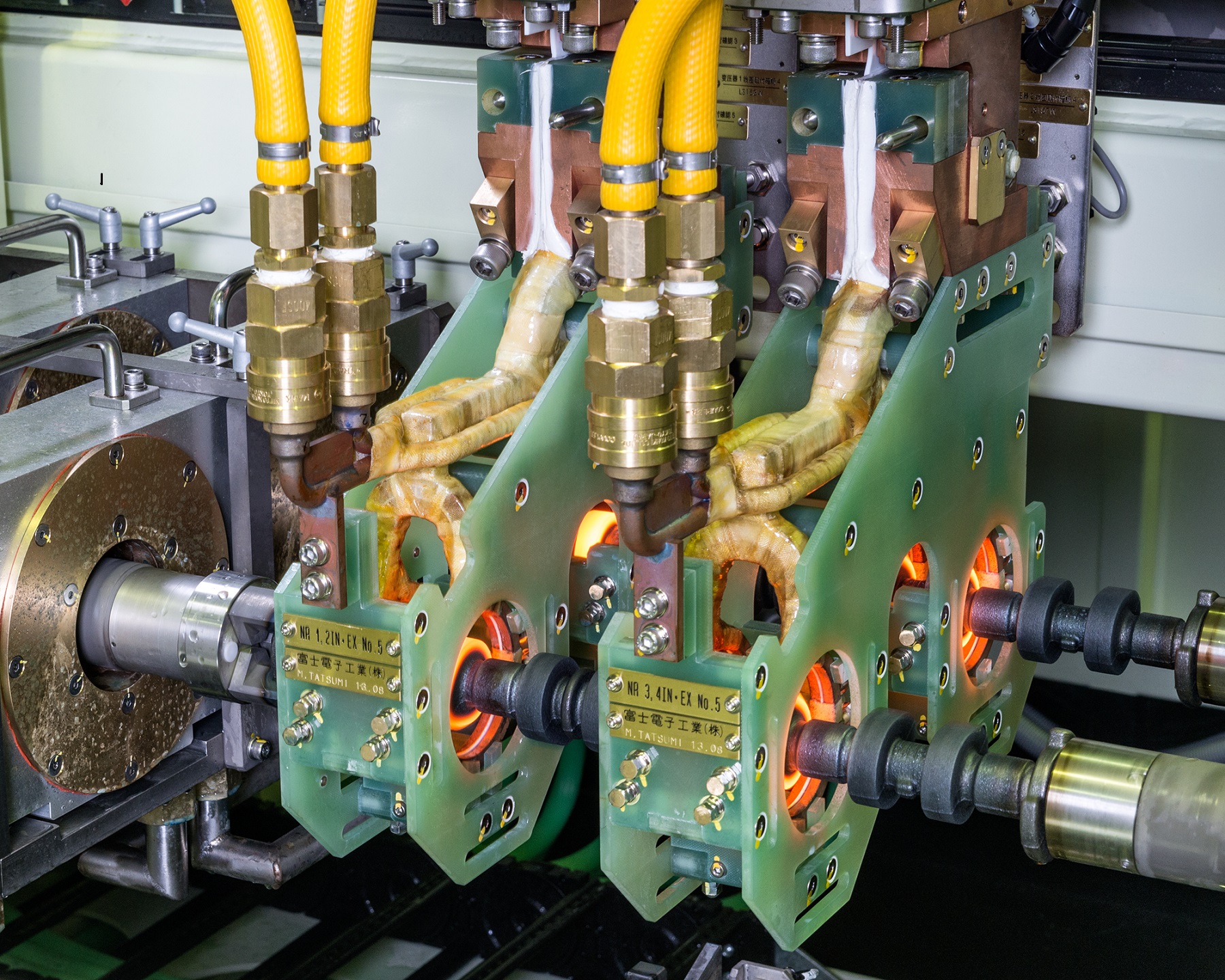
The photo shows our 1-cylinder engine crankshaft induction hardening machine.
The crankshaft is used in engines for agricultural and production machinery.
This machine is installed in an overseas engine plant.
The workpiece is transported from the previous process and hardened.
Loading and unloading is done manually, while door close → coil set →
hardening is automatic.
(In recent years robotics have been implemented for loading and unloading,
resulting in an increase in fully automatic machines.)
In the photo, in the front left is the hardening machine.
In the back right is the incoming panel and transistorized converter.
In the back left is the quenching water tank and air-cooled chiller.
Both pin and journal sections are hardened at the same station,
allowing for a compact machine design.
~Crankshaft Induction Hardening Agricultural Machinery Production Machinery
Engine Parts IH Heat Treat~
The photo shows the hardening and reheating stations in a automobile propeller
center bearing shaft induction hardening and reheating machine.
On the right with the green spray quenching jacket is the hardening station.
On the left in the brown box is the reheating station.
※At Fuji Denshi, we refer to tempering as reheating to differentiate from
furnace methods.
The hardening and reheating stations are divided and have separate converters
to achieve a cycle time of under 30 seconds.
This design achieves both compactness and high productivity.

We manufacture driveshaft induction hardening machines.
[Machine Features]
① High productivity of 225 parts/hour
② Single shot method for 40~50% energy savings versus scan hardening
③ Case depth of over 40% of diameter to achieve high fatigue strength
④ Originally developed straightening roller to prevent run out during hardening
Please contact us for your questions and concerns about driveshaft hardening.
~Driveshaft Induction Hardening High Productivity Energy Savings
Fatigue Strength Low Runout~
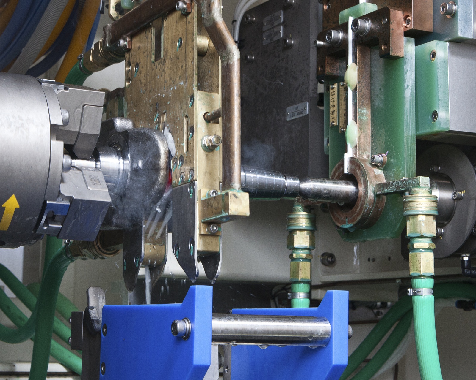
[Custom-made Machines]
The photo shows the hardening station of our one-cylinder
engine crankshaft induction hardening machine.
This type of engine is supplied for agricultural and production machinery.
This machine is installed in an overseas engine plant.
The workpiece is transported from the previous process and hardened.
Loading and unloading is done manually,
while door close → coil set → hardening is automatic.
(In recent years robotics have been implemented for loading and unloading,
resulting in an increase in fully automatic machines.)
In the photo, the crankshaft is rotated while the pin section is hardened.
The gold-colored device hanging to the left is the pin hardening coil,
and the copper-colored device attached to green insulation on the right
is the journal hardening coil.
Both pin and journal sections are hardened at the same station,
allowing for a compact machine design.

The photo shows our all-purpose single axle double head
vertical scan induction hardening machine.
This machine is installed in an induction heat treat plant
and can treat workpieces up to Φ150 and length 1.5m.
One converter supplies power in alternation to two hardening stations.
Our vertical scan induction hardening machines typically move the coil
during scanning, but this machine was designed for the workpiece
to move as specified by our customer.
By setting the work feed speed and length, repeated automatic heating
for the same workpiece is easily achieved.
This machine is adaptable for high volume production of the same workpiece
and also flexible production for various workpieces.
[Applications of Induction Heating]
● Pipe Rolling and Welding
Pipe seam and fin tube continuous welding, hoop and core welding,
pipe preheating
● Coating
Compact motor insulation resin coating, pipe antioxidizing layer coating
● Getters
Electrical tubes, neon tubes, display tubes, mercury lamps,
gas purge for flourescent lights, flash getters
● Semiconductors
Silicon monocrystal growth, epitaxial growth
● Cast Manufacturing
Heating of extrusion nozzle and forming dice, aluminum extrusion heating
● Heat Cycle Experiment
Metallic material heat cycle experiment, educational materials
● Annealing
Annealing of wires and stainless steel pipes, press pre-processing
including shaping and bending
Fuji Denshi's heating power units can be used for all of these applications
in addition to the hardening of steel parts.
Please contact us with any and all of your heating needs.
~Induction Induction Heating Applications Hardening~

► Challenges faced by the Automotive Industry
In the automotive industry, suspension members are critical structural components that influence both vehicle safety and ride comfort. In recent years, there has been a growing demand for both weight reduction and high rigidity, making it particularly challenging to ensure welding quality.
Suspension components require both high welding strength and dimensional accuracy. In particular, suspension members directly absorb impacts from suspension parts, making welding reliability crucial for overall vehicle safety.
► Technical Challenges
Key challenges in manufacturing suspension members:
・Controlling thermal distortion caused by welding
・Ensuring uniform welding quality in complex shapes
・Establishing optimal welding conditions to reduce spatter adhesion
・Overcoming welding difficulties due to gaps between materials and differences in plate thickness
[Problem Solving with Welding Technology]
Through years of prototype development, we have established the following solutions with our unique welding technology:
✔ Development of a Thermal Deformation Control System
・ Suppressing distortion through optimized welding sequences and positions
・ Ensuring dimensional accuracy with custom-developed welding jigs
・ Managing heat input through machine-monitored current control
✔ Quality Assurance System
・ Full inspection using 3D measurement
・ Strength verification through destructive testing
・ Weld defect detection via macro inspections
►Proven Reliability
○ Customer Feedback
The stability of welding quality is outstanding.
I was amazed by the high dimensional accuracy.
The quick turnaround time is impressive.
►Implementation Benefits
Feedback from companies that have implemented our solutions:
・ Defect rate: Reduced by 75% compared to conventional methods
・ Manufacturing lead time: Shortened by 20%
・ Overall costs: Reduced by 15%
*For more detailed case studies and performance data, please download our technical materials from the link below:
Technical Materials Download: https://ja.nc-net.or.jp/company/22325/dl/catalog/207206
For any inquiries, please feel free to contact us via our technical consultation and quotation request form.
Technical Consultation & Quotation Request: https://ja.nc-net.or.jp/company/22325/inquiry/
[Company Profile]
Company Name: Timec Co., Ltd.
Address: 197-1 Nishigori, Soja City, Okayama, 719-1164, Japan
TEL: +81-866-93-1269
FAX: +81-866-93-2540
Corporate Website: https://timec.co.jp/
Related URL: https://timec.co.jp/mind/

[Case Study]
Sheet Metal Fabrication of Intake Manifold (Aluminum Die-Cast)
– Achieving Shorter Prototype Lead Time and Cost Reduction in Mass Production –
► Recognizing the Challenges
In the 1990s, aluminum die-casting was the dominant manufacturing method for intake manifolds in the automotive industry. However, rising raw material costs and increased manufacturing expenses due to multi-cylinder engine designs led many parts manufacturers to seek alternative production methods.
Key challenges during the prototyping phase included:
・High cost of mold production
・Lengthy prototype lead times
・Limited flexibility in design modifications
・High costs for small-batch production
►Technical Approach
Our proposed sheet metal fabrication method offers a revolutionary approach that significantly reduces manufacturing costs compared to traditional aluminum die-casting.
Key technical points include:
・Material Selection: SPHC (hot-rolled steel plate) and STKM (carbon steel mechanical tubing)
・Optimized Design: Strength analysis and weight reduction using 3D CAD
・Manufacturing Process: Combination of press forming, laser processing, and welding technology
・Quality Assurance: High-precision dimensional verification using 3D measuring instruments
►Detailed Solutions
The sheet metal fabrication of the intake manifold was developed through the following phases:
1. Design Phase
・3D modeling using CAD
・Design of press molds and jigs for laser processing and welded assembly
・Development of DNC machining programs based on 3D models
2. Prototype Phase
・Mold and jig processing using DNC machining
・High-precision machining with a 5-axis laser cutter
・Precision welding by skilled technicians
3. Validation Phase
・Dimensional verification using 3D measuring instruments
・Performance evaluation through actual vehicle installation tests, followed by design optimization
・Durability testing and feedback-driven design improvements
►Implementation Benefits
This development project achieved the following results:
✔ Manufacturing Cost: Reduced by 40% compared to conventional methods
✔ Development Period: Prototype lead time shortened by 50%
✔ Weight Reduction: 20% lighter than conventional
✔ Design Flexibility: Significantly improved
These achievements were made possible by over 50 years of prototype development experience and a team of 160 skilled engineers. We continue to apply this technology to the sheet metal fabrication of various automotive components.
►Future Prospects
In recent years, some intake manifolds have transitioned to resin materials. However, the optimal manufacturing method depends on the required component characteristics and operating environment.
We propose the best manufacturing solutions, including sheet metal fabrication and hybrid approaches, tailored to each customer’s needs.
►Conclusion
Sheet metal fabrication of intake manifolds is a highly effective solution that achieves both cost reduction and weight savings.
For more details, please download our technical documents from the link below and discuss potential applications with your development team.
[Company Profile]
Company Name: Timec Co., Ltd.
Address: 197-1 Nishigori, Soja City, Okayama, 719-1164, Japan
TEL: +81-866-93-1269
FAX: +81-866-93-2540
Corporate Website: https://timec.co.jp/
🔹 Download Technical Documents:
https://ja.nc-net.or.jp/company/22325/dl/catalog/207206
🔹 Technical Consultation & Quotation Requests:
https://ja.nc-net.or.jp/company/22325/inquiry/
🔹 Related URL: https://timec.co.jp/

Oil Pan Prototyping and Development – A Critical Component for Engine & Transmission Performance
In the automotive industry, the oil pan plays a crucial role in ensuring the performance and reliability of engines and transmissions. This guide, based on over 50 years of experience in prototype development, addresses the challenges and solutions in oil pan manufacturing.
Key Challenges in Oil Pan Development
Currently, the automotive industry faces several challenges in oil pan production:
1. Strict control over material thickness reduction
2. High-precision surface quality for mounting areas
3. Reduction of lead time from prototyping to mass production
4. Maintaining cost competitiveness
Particularly in deep drawing press forming of oil pans using mild steel sheets, precise control over material thickness reduction is essential.
Customer Feedback:
Since these parts are used around the engine and transmission, oil leakage is absolutely unacceptable.
Technical Solutions
To address these challenges, we implement the following technological approaches:
1. Deep Drawing and Press Forming Simulation
Pre-evaluation using JSTAMP software
Prediction and optimization of material thickness reduction rates
Prevention of forming defects in advance
High-Precision Die Design & Manufacturing
2. High-Precision Die Design and Manufacturing
Precision design using 3D CAD
Uniform surface pressure distribution with unique die structure
Finishing by skilled technicians
3. Quality Assurance System
100% inspection with 3D measuring machines
Verification of mounting surfaces with dedicated inspection jigs
Operation of traceability system
Actual case studies have shown the following improvements:
✔ Prototyping period: Reduced by 30% compared to conventional methods
✔ Cost: Lowered by 30% compared to traditional techniques
✔ Mass production transition: Smooth and efficient ramp-up
Our expertise in deep drawing press forming, particularly in controlling material thickness reduction, is what sets us apart in manufacturing oil pans for engine and transmission components.
Founder’s Comment:
Only real technology can meet such strict requirements.
Proposal to Customers
We have even more detailed technical documents available. You can download them for free from the following URL:
https://ja.nc-net.or.jp/company/22325/dl/catalog/207206
Please feel free to contact us from the following form for technical consultations and quotation requests:
https://ja.nc-net.or.jp/company/22325/inquiry/
[Company Profile]
Company Name: Timec Co., Ltd.
Location: 197-1 Nishigori, Soja City, Okayama Prefecture 719-1164
TEL: 0866-93-1269
FAX: 0866-93-2540
Corporate Website:
https://timec.co.jp/
Related URL: https://timec.co.jp/

► Industry Challenges
Are you facing challenges in the seamless transition from prototyping to mass production of seat leg parts in manufacturing?
In the automotive industry, manufacturers must balance lightweight design, high strength, cost reduction, and short lead times, which often have conflicting requirements.
Additionally, interference checks with surrounding seat components and assembly feasibility validation require precise adjustments. The quality of the prototype phase directly affects mass production efficiency.
► Our Approach to Solutions
With over 50 years of expertise in prototype development, we provide optimal solutions tailored to our customers' needs.
Our Strengths in Seat Leg Component Production:
✔ Proposals from the design stage using 3D CAD
✔ Preliminary validation with press forming simulation
✔ Comprehensive support from material selection to processing methods
✔ Ultra-short lead times enabled by 24-hour operations
We offer the following specialized services for seat leg parts:
✔ Material: SPH, STKM, and other optimal materials based on application needs
✔ Processing: Single-unit press processing and pipe processing
✔ Assembly: Integrated welding assembly and surface treatment
► Technical Features
【Equipment Capabilities】
✔ 1,200-ton large press machines for high-precision processing
✔ 3D laser processing machines for complex shapes
✔ Robotic welding systems for high-quality joining
✔ 3D measuring machines for precise quality control
【Manufacturing Process Strengths】
1. Design Support
Equipped with CATIA and multiple 3D CAD systems
Conducts interference checks with surrounding seat components
Offers design proposals optimized for assembly feasibility
2. Prototype Manufacturing
Short lead times utilizing state-of-the-art manufacturing equipment
High-precision processing by skilled technicians
Quality stabilization using custom jigs
3. Small-Lot Production
Flexible support for small-lot production after prototyping
ISO9001-certified quality control system
► Proven Benefits
Our clients have experienced the following improvements:
✔ 30% reduction in development time
✔ 25% reduction in prototyping costs
✔ Streamlined transition to mass production
✔ Significant reduction in quality defects
★ Success Story
We were looking for a manufacturing partner that could handle everything from prototyping to small-lot production of seat leg components. By working with your company, we achieved faster development and stabilized quality.
— Major Automotive Parts Manufacturer
► Delivering Even Greater Value
For a detailed technical guide, download our free materials here:
🔗 Download Technical Documents
https://ja.nc-net.or.jp/company/22325/dl/catalog/207206
For technical consultations and quotations, please use the form below:
🔗 Inquiry Form
https://ja.nc-net.or.jp/company/22325/inquiry/
【Company Information】
Timec Co., Ltd.
📍 197-1 Nishikoori, Soja City, Okayama, 719-1164, Japan
📞 TEL: 0866-93-1269
📠 FAX: 0866-93-2540
🌐 Website: https://timec.co.jp/
🔗 Related URL: https://timec.co.jp/
[Custom-made Machines]
Construction Machinery Parts Hardening Machine
[Overview]
This construction machinery parts hardening machine is installed
with a 570kW, 10kHz transistorized converter.
This is our induction hardenig machine for idlers and truck rollers used
in the continuous track of agricultural machinery such as combines.
This machine can perform induction hardening of up to 20 types of
cast metal parts by changing the coils and jigs.
The workpiece is loaded and unloaded by robot from above
the hardening station, achieving high productivity and flexibility.
The semi-open line coil, designed to match the outer diameter of the workpiece,
and the capacitor bank move horizontally during loading/unloading.
The cooling unit, seen in the photo on the back right of the hardening machine,
is located for compactness and easy access for maintenance.

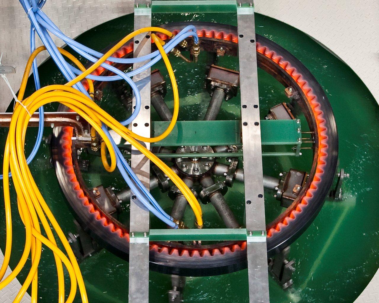
The photo shows our induction hardening machine for
construction machinery slew bearings.
The section hardened is the inner gear inside the ring.
This machine can treat parts up to 1300mm in diameter and
over 250kg in weight.
To provide the large energy required for heating, this machine is equipped
with a 1100kW, 10kHz converter.
While induction hardening of large gears can cause cracking and runout,
our machine achieves an even casing by heating the workpiece in two stages,
preheating and main heating, and quenching using our dip-spray method.
In the photo, the octagonal-shaped pool to the left is the dip spray tank.
The workpiece is sitting on the receive jig and diagonally above it is the coil.
During loading/unloading, the coil moves to the right, and during hardening
it moves directly above the workpiece.
Dip quenching requires a high volume of quenching water.
This machine utilizes a magnet separator and oil skimmer to remove impurities
and the quenching water is recycled into the tank.
The machine design was kept as compact as possible despite
treating extremely large workpieces.

The photo shows the hardening station of our induction hardening machine
for construction machinery slew bearings.
The section hardened is the inner gear inside the ring.
This machine can treat parts up to 1300mm in diameter
and over 250kg in weight.
In the photo, the workpiece is lifted by the receive jig into the ring-shaped coil,
which induction heats the gear inner circumference.
After heating, the jig carries the workpiece down and submerges it
in the quenching water tank. There it is sprayed by quenching water jackets
to achieve even quenching.
While induction hardening of large gears can cause cracking and runout,
our machine achieves an even casing by heating the workpiece in two stages,
preheating and main heating, and quenching using our dip-spray method.
This is our induction hardening machine for idlers and track rollers used
in the continuous track of agricultural machinery such as combines.
Our specialized semi-open coil heats the rotating workpiece while the
inner surface is quenched by quenching water sprayed from the jigs.
While the varying material content of cast iron products such as this idler
make hardening difficult, we were able to achieve stable hardening through
detailed coil design and extensive trial and error calibration.
The inner surface quenching helps to prevent cracking and ensure
quality hardening.
~Induction Hardening Cracking Idler Roller Agricultural Machinery
IH Heat Treat~


