Language: 日本語 | English
Language: 日本語 | English

► Challenges faced by the Automotive Industry
In the automotive industry, suspension members are critical structural components that influence both vehicle safety and ride comfort. In recent years, there has been a growing demand for both weight reduction and high rigidity, making it particularly challenging to ensure welding quality.
Suspension components require both high welding strength and dimensional accuracy. In particular, suspension members directly absorb impacts from suspension parts, making welding reliability crucial for overall vehicle safety.
► Technical Challenges
Key challenges in manufacturing suspension members:
・Controlling thermal distortion caused by welding
・Ensuring uniform welding quality in complex shapes
・Establishing optimal welding conditions to reduce spatter adhesion
・Overcoming welding difficulties due to gaps between materials and differences in plate thickness
[Problem Solving with Welding Technology]
Through years of prototype development, we have established the following solutions with our unique welding technology:
✔ Development of a Thermal Deformation Control System
・ Suppressing distortion through optimized welding sequences and positions
・ Ensuring dimensional accuracy with custom-developed welding jigs
・ Managing heat input through machine-monitored current control
✔ Quality Assurance System
・ Full inspection using 3D measurement
・ Strength verification through destructive testing
・ Weld defect detection via macro inspections
►Proven Reliability
○ Customer Feedback
The stability of welding quality is outstanding.
I was amazed by the high dimensional accuracy.
The quick turnaround time is impressive.
►Implementation Benefits
Feedback from companies that have implemented our solutions:
・ Defect rate: Reduced by 75% compared to conventional methods
・ Manufacturing lead time: Shortened by 20%
・ Overall costs: Reduced by 15%
*For more detailed case studies and performance data, please download our technical materials from the link below:
Technical Materials Download: https://ja.nc-net.or.jp/company/22325/dl/catalog/207206
For any inquiries, please feel free to contact us via our technical consultation and quotation request form.
Technical Consultation & Quotation Request: https://ja.nc-net.or.jp/company/22325/inquiry/
[Company Profile]
Company Name: Timec Co., Ltd.
Address: 197-1 Nishigori, Soja City, Okayama, 719-1164, Japan
TEL: +81-866-93-1269
FAX: +81-866-93-2540
Corporate Website: https://timec.co.jp/
Related URL: https://timec.co.jp/mind/

[Case Study]
Sheet Metal Fabrication of Intake Manifold (Aluminum Die-Cast)
– Achieving Shorter Prototype Lead Time and Cost Reduction in Mass Production –
► Recognizing the Challenges
In the 1990s, aluminum die-casting was the dominant manufacturing method for intake manifolds in the automotive industry. However, rising raw material costs and increased manufacturing expenses due to multi-cylinder engine designs led many parts manufacturers to seek alternative production methods.
Key challenges during the prototyping phase included:
・High cost of mold production
・Lengthy prototype lead times
・Limited flexibility in design modifications
・High costs for small-batch production
►Technical Approach
Our proposed sheet metal fabrication method offers a revolutionary approach that significantly reduces manufacturing costs compared to traditional aluminum die-casting.
Key technical points include:
・Material Selection: SPHC (hot-rolled steel plate) and STKM (carbon steel mechanical tubing)
・Optimized Design: Strength analysis and weight reduction using 3D CAD
・Manufacturing Process: Combination of press forming, laser processing, and welding technology
・Quality Assurance: High-precision dimensional verification using 3D measuring instruments
►Detailed Solutions
The sheet metal fabrication of the intake manifold was developed through the following phases:
1. Design Phase
・3D modeling using CAD
・Design of press molds and jigs for laser processing and welded assembly
・Development of DNC machining programs based on 3D models
2. Prototype Phase
・Mold and jig processing using DNC machining
・High-precision machining with a 5-axis laser cutter
・Precision welding by skilled technicians
3. Validation Phase
・Dimensional verification using 3D measuring instruments
・Performance evaluation through actual vehicle installation tests, followed by design optimization
・Durability testing and feedback-driven design improvements
►Implementation Benefits
This development project achieved the following results:
✔ Manufacturing Cost: Reduced by 40% compared to conventional methods
✔ Development Period: Prototype lead time shortened by 50%
✔ Weight Reduction: 20% lighter than conventional
✔ Design Flexibility: Significantly improved
These achievements were made possible by over 50 years of prototype development experience and a team of 160 skilled engineers. We continue to apply this technology to the sheet metal fabrication of various automotive components.
►Future Prospects
In recent years, some intake manifolds have transitioned to resin materials. However, the optimal manufacturing method depends on the required component characteristics and operating environment.
We propose the best manufacturing solutions, including sheet metal fabrication and hybrid approaches, tailored to each customer’s needs.
►Conclusion
Sheet metal fabrication of intake manifolds is a highly effective solution that achieves both cost reduction and weight savings.
For more details, please download our technical documents from the link below and discuss potential applications with your development team.
[Company Profile]
Company Name: Timec Co., Ltd.
Address: 197-1 Nishigori, Soja City, Okayama, 719-1164, Japan
TEL: +81-866-93-1269
FAX: +81-866-93-2540
Corporate Website: https://timec.co.jp/
🔹 Download Technical Documents:
https://ja.nc-net.or.jp/company/22325/dl/catalog/207206
🔹 Technical Consultation & Quotation Requests:
https://ja.nc-net.or.jp/company/22325/inquiry/
🔹 Related URL: https://timec.co.jp/

Oil Pan Prototyping and Development – A Critical Component for Engine & Transmission Performance
In the automotive industry, the oil pan plays a crucial role in ensuring the performance and reliability of engines and transmissions. This guide, based on over 50 years of experience in prototype development, addresses the challenges and solutions in oil pan manufacturing.
Key Challenges in Oil Pan Development
Currently, the automotive industry faces several challenges in oil pan production:
1. Strict control over material thickness reduction
2. High-precision surface quality for mounting areas
3. Reduction of lead time from prototyping to mass production
4. Maintaining cost competitiveness
Particularly in deep drawing press forming of oil pans using mild steel sheets, precise control over material thickness reduction is essential.
Customer Feedback:
Since these parts are used around the engine and transmission, oil leakage is absolutely unacceptable.
Technical Solutions
To address these challenges, we implement the following technological approaches:
1. Deep Drawing and Press Forming Simulation
Pre-evaluation using JSTAMP software
Prediction and optimization of material thickness reduction rates
Prevention of forming defects in advance
High-Precision Die Design & Manufacturing
2. High-Precision Die Design and Manufacturing
Precision design using 3D CAD
Uniform surface pressure distribution with unique die structure
Finishing by skilled technicians
3. Quality Assurance System
100% inspection with 3D measuring machines
Verification of mounting surfaces with dedicated inspection jigs
Operation of traceability system
Actual case studies have shown the following improvements:
✔ Prototyping period: Reduced by 30% compared to conventional methods
✔ Cost: Lowered by 30% compared to traditional techniques
✔ Mass production transition: Smooth and efficient ramp-up
Our expertise in deep drawing press forming, particularly in controlling material thickness reduction, is what sets us apart in manufacturing oil pans for engine and transmission components.
Founder’s Comment:
Only real technology can meet such strict requirements.
Proposal to Customers
We have even more detailed technical documents available. You can download them for free from the following URL:
https://ja.nc-net.or.jp/company/22325/dl/catalog/207206
Please feel free to contact us from the following form for technical consultations and quotation requests:
https://ja.nc-net.or.jp/company/22325/inquiry/
[Company Profile]
Company Name: Timec Co., Ltd.
Location: 197-1 Nishigori, Soja City, Okayama Prefecture 719-1164
TEL: 0866-93-1269
FAX: 0866-93-2540
Corporate Website:
https://timec.co.jp/
Related URL: https://timec.co.jp/

► Industry Challenges
Are you facing challenges in the seamless transition from prototyping to mass production of seat leg parts in manufacturing?
In the automotive industry, manufacturers must balance lightweight design, high strength, cost reduction, and short lead times, which often have conflicting requirements.
Additionally, interference checks with surrounding seat components and assembly feasibility validation require precise adjustments. The quality of the prototype phase directly affects mass production efficiency.
► Our Approach to Solutions
With over 50 years of expertise in prototype development, we provide optimal solutions tailored to our customers' needs.
Our Strengths in Seat Leg Component Production:
✔ Proposals from the design stage using 3D CAD
✔ Preliminary validation with press forming simulation
✔ Comprehensive support from material selection to processing methods
✔ Ultra-short lead times enabled by 24-hour operations
We offer the following specialized services for seat leg parts:
✔ Material: SPH, STKM, and other optimal materials based on application needs
✔ Processing: Single-unit press processing and pipe processing
✔ Assembly: Integrated welding assembly and surface treatment
► Technical Features
【Equipment Capabilities】
✔ 1,200-ton large press machines for high-precision processing
✔ 3D laser processing machines for complex shapes
✔ Robotic welding systems for high-quality joining
✔ 3D measuring machines for precise quality control
【Manufacturing Process Strengths】
1. Design Support
Equipped with CATIA and multiple 3D CAD systems
Conducts interference checks with surrounding seat components
Offers design proposals optimized for assembly feasibility
2. Prototype Manufacturing
Short lead times utilizing state-of-the-art manufacturing equipment
High-precision processing by skilled technicians
Quality stabilization using custom jigs
3. Small-Lot Production
Flexible support for small-lot production after prototyping
ISO9001-certified quality control system
► Proven Benefits
Our clients have experienced the following improvements:
✔ 30% reduction in development time
✔ 25% reduction in prototyping costs
✔ Streamlined transition to mass production
✔ Significant reduction in quality defects
★ Success Story
We were looking for a manufacturing partner that could handle everything from prototyping to small-lot production of seat leg components. By working with your company, we achieved faster development and stabilized quality.
— Major Automotive Parts Manufacturer
► Delivering Even Greater Value
For a detailed technical guide, download our free materials here:
🔗 Download Technical Documents
https://ja.nc-net.or.jp/company/22325/dl/catalog/207206
For technical consultations and quotations, please use the form below:
🔗 Inquiry Form
https://ja.nc-net.or.jp/company/22325/inquiry/
【Company Information】
Timec Co., Ltd.
📍 197-1 Nishikoori, Soja City, Okayama, 719-1164, Japan
📞 TEL: 0866-93-1269
📠 FAX: 0866-93-2540
🌐 Website: https://timec.co.jp/
🔗 Related URL: https://timec.co.jp/
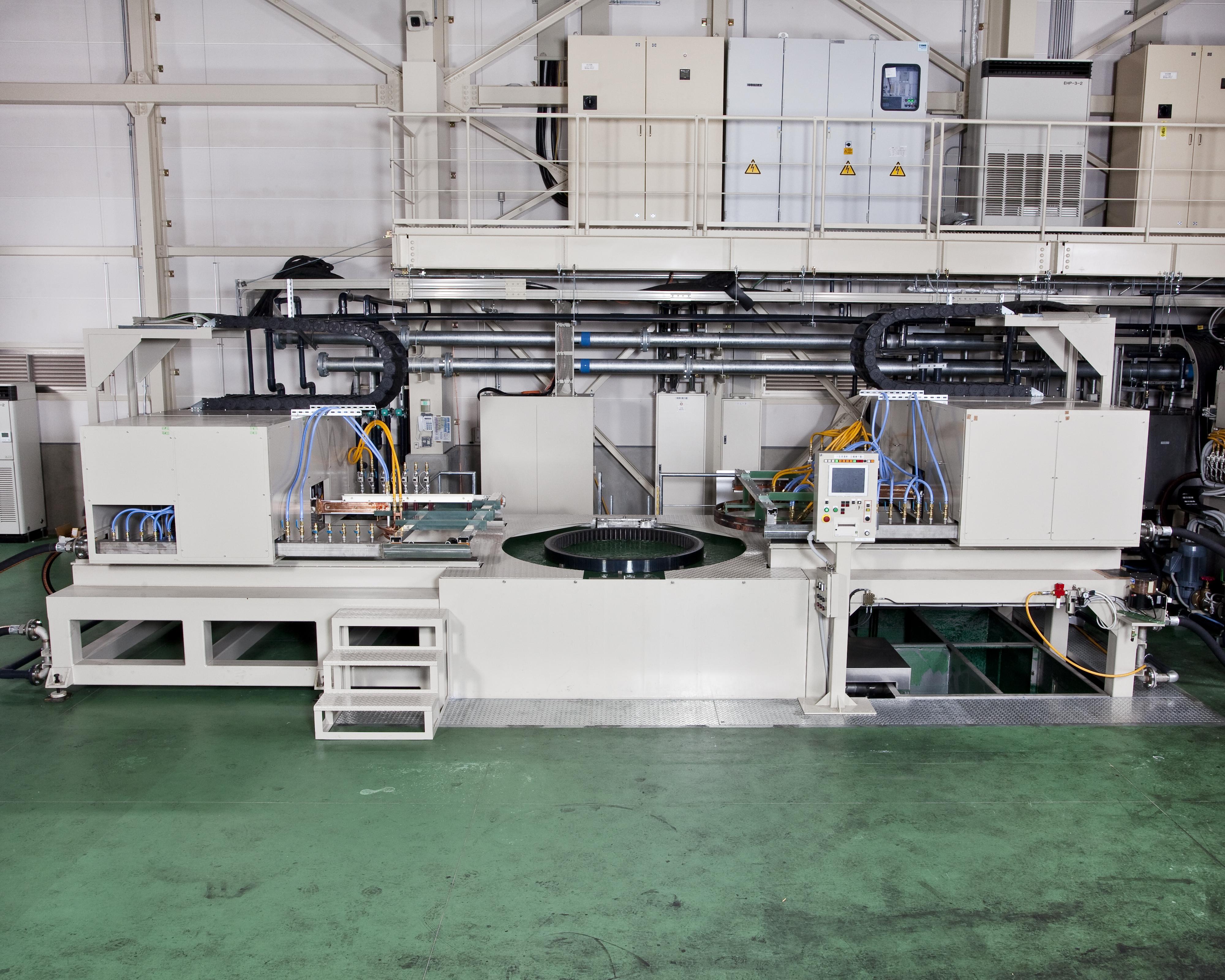
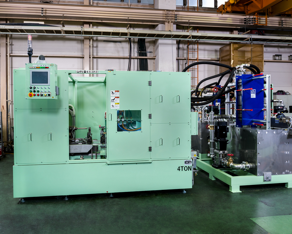
In house assembled oversize carburizing machine.
[Main Product] Bearing race, large size internal gear, large size gear
✔ Max. φ1800×(H)400mm
[Material] Carbon steel (S45C), Stainless steel (SUS304)
[Single Quench]
For transfer quenching, starting and ending point of heating and cooling overlaps leading to cracks or reduced hardness.
With Fuji Electronic all around single shot quenching, a complete uniformed quenching layer can be produced even a slewing ring size of diameter of 1.8m and module of 15. Also, comparing to transfer quenching, improved productivity, 1/5 work speed, and 1/2 ~ 1/3 electricity consumption.
[Carburizing]
Once the heating process has completed, by simultaneously dipping the product into the cooling water and blasting water current through jackets, helps to prevent from entering while forming a uniformed quenched layer.
In addition, by controlling quenching water temperature and stir speed, an effect layer can be controlled precisely.
[Inner and Outer Diameter Simultaneously Heating]
By having two electrical switches on both sides, the inner and outer layer can be quenched simultaneously with low distortion.
[Custom-made Machines]
Construction Machinery Parts Hardening Machine
[Overview]
This construction machinery parts hardening machine is installed
with a 570kW, 10kHz transistorized converter.
The photo shows our 1-cylinder engine crankshaft induction hardening machine.
The crankshaft is used in engines for agricultural and production machinery.
This machine is installed in an overseas engine plant.
The workpiece is transported from the previous process and hardened.
Loading and unloading is done manually, while door close → coil set →
hardening is automatic.
(In recent years robotics have been implemented for loading and unloading,
resulting in an increase in fully automatic machines.)
In the photo, in the front left is the hardening machine.
In the back right is the incoming panel and transistorized converter.
In the back left is the quenching water tank and air-cooled chiller.
Both pin and journal sections are hardened at the same station,
allowing for a compact machine design.
~Crankshaft Induction Hardening Agricultural Machinery Production Machinery
Engine Parts IH Heat Treat~
This is our induction hardenig machine for idlers and truck rollers used
in the continuous track of agricultural machinery such as combines.
This machine can perform induction hardening of up to 20 types of
cast metal parts by changing the coils and jigs.
The workpiece is loaded and unloaded by robot from above
the hardening station, achieving high productivity and flexibility.
The semi-open line coil, designed to match the outer diameter of the workpiece,
and the capacitor bank move horizontally during loading/unloading.
The cooling unit, seen in the photo on the back right of the hardening machine,
is located for compactness and easy access for maintenance.

[Job Heat Treatment]
The photo shows our custom-made large dip quench hardening machine.
[Major workpiece types] bearing race, large internal gear, large gear
※ Outer diameter: up to Φ1800, thickness 350mm
※ Inner diameter: up to Φ1500, thickness 150mm
[Material] steel (S45C), stainless steel (SUS304), etc.
[One-Shot Hardening]
During scan hardening, the beginning and end points are heated
and quenched twice, which can cause cracking or soft spots.
In contrast, our one-shot hardening achieves a sufficiently deep casing
around the whole circumference of gears up to 1.8m diameter and 15 module.
[Dip Quench Hardening]
Immediately after heating, the workpiece is submerged in quenching water
and sprayed by quenching water jackets. This prevents the formation of
an air layer around the workpiece and ensures an even casing.
By controlling the water temperature and mixing speed,
the resultant casing can be controlled to high precision.
[Inner/Outer Simultaenous Heating]
The machine can be fitted with two power sources to heat the
inner and outer surfaces at the same time.

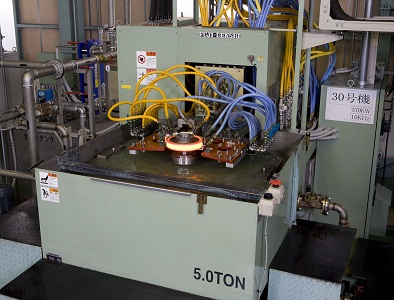
The photo shows our induction hardening machine for
construction machinery slew bearings.
The section hardened is the inner gear inside the ring.
This machine can treat parts up to 1300mm in diameter and
over 250kg in weight.
To provide the large energy required for heating, this machine is equipped
with a 1100kW, 10kHz converter.
While induction hardening of large gears can cause cracking and runout,
our machine achieves an even casing by heating the workpiece in two stages,
preheating and main heating, and quenching using our dip-spray method.
In the photo, the octagonal-shaped pool to the left is the dip spray tank.
The workpiece is sitting on the receive jig and diagonally above it is the coil.
During loading/unloading, the coil moves to the right, and during hardening
it moves directly above the workpiece.
Dip quenching requires a high volume of quenching water.
This machine utilizes a magnet separator and oil skimmer to remove impurities
and the quenching water is recycled into the tank.
The machine design was kept as compact as possible despite
treating extremely large workpieces.

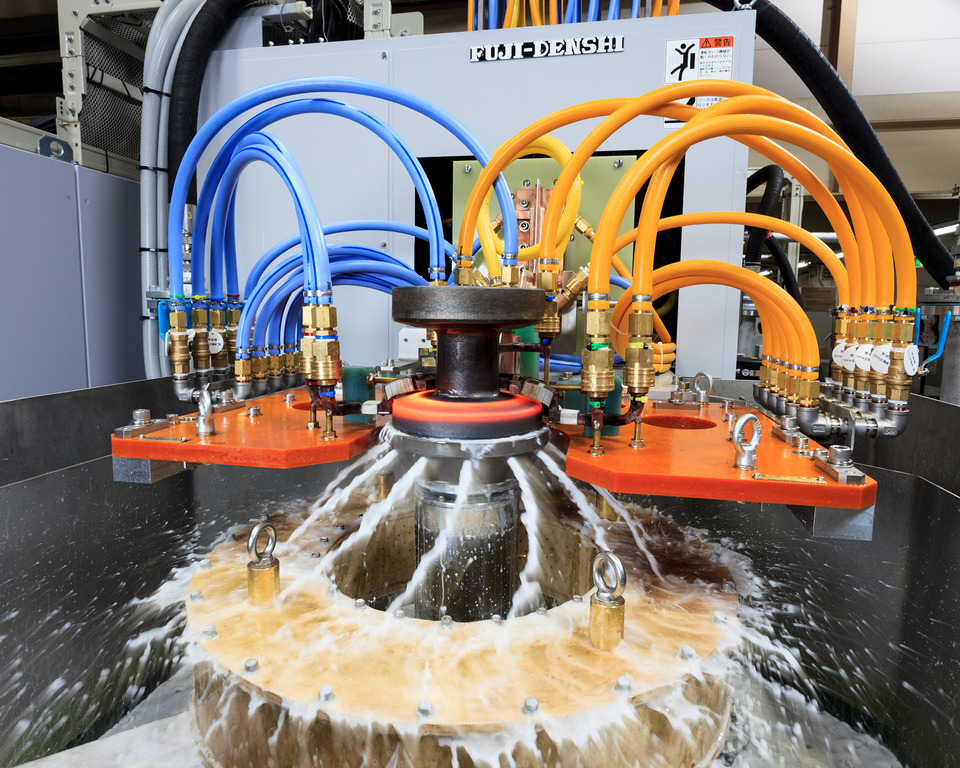
The photo shows the hardening station of our induction hardening machine
for construction machinery slew bearings.
The section hardened is the inner gear inside the ring.
This machine can treat parts up to 1300mm in diameter
and over 250kg in weight.
In the photo, the workpiece is lifted by the receive jig into the ring-shaped coil,
which induction heats the gear inner circumference.
After heating, the jig carries the workpiece down and submerges it
in the quenching water tank. There it is sprayed by quenching water jackets
to achieve even quenching.
While induction hardening of large gears can cause cracking and runout,
our machine achieves an even casing by heating the workpiece in two stages,
preheating and main heating, and quenching using our dip-spray method.
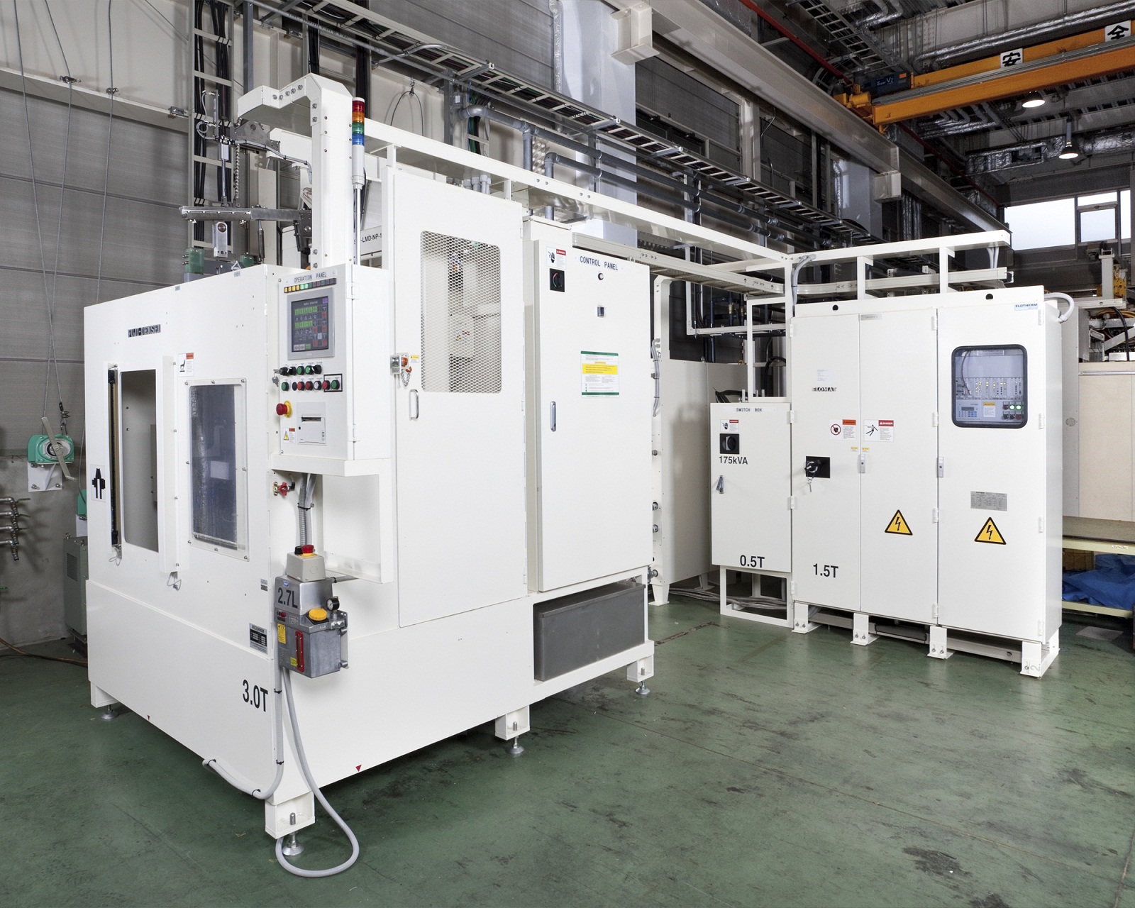
[Custom-made Machines]
The pictured machine is our horizontal scan induction hardening
and reheat machine for construction machinery shafts.
At Fuji Denshi, we refer to tempering as reheating to differentiate
from furnace methods.
The pictured machine is specified for front loading and unloading.
Loading is performed by robot and unloading is done automatically
by jigs and chute for a simple yet highly productive design.
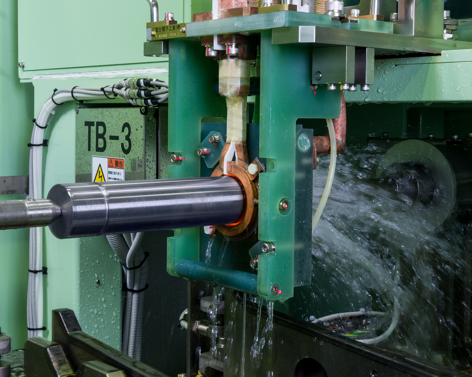
[Custom-made Machines]
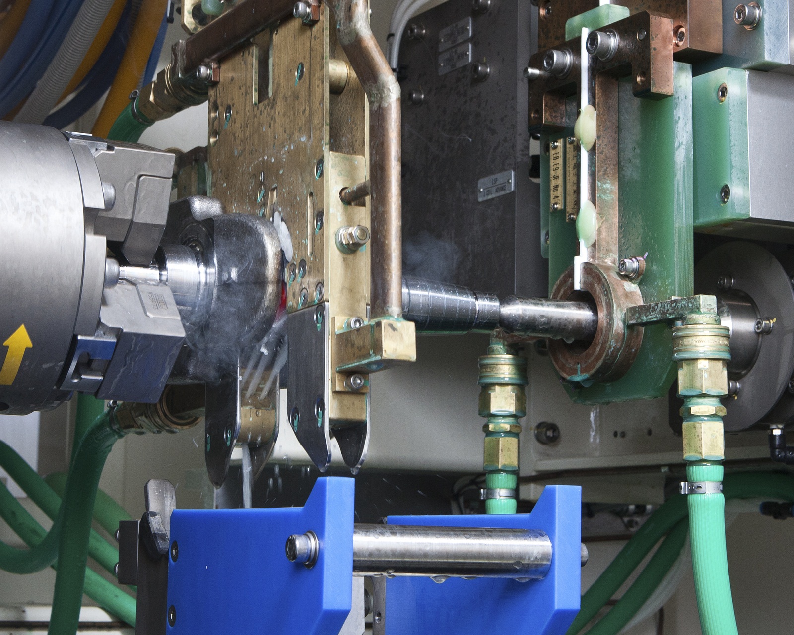
The photo shows the hardening station of our one-cylinder
engine crankshaft induction hardening machine.
This type of engine is supplied for agricultural and production machinery.
This machine is installed in an overseas engine plant.
The workpiece is transported from the previous process and hardened.
Loading and unloading is done manually,
while door close → coil set → hardening is automatic.
(In recent years robotics have been implemented for loading and unloading,
resulting in an increase in fully automatic machines.)
In the photo, the crankshaft is rotated while the pin section is hardened.
The gold-colored device hanging to the left is the pin hardening coil,
and the copper-colored device attached to green insulation on the right
is the journal hardening coil.
Both pin and journal sections are hardened at the same station,
allowing for a compact machine design.
At Fuji Denshi, we manufacture high frequency induction heating machines.
We also have a heat treat plant at our headquarters In Yao, Osaka.
While we consider induction hardening our specialty,
we have also developed many technologies in other fields.
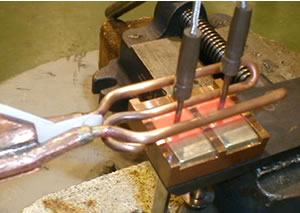
The photo shows brazing by induction. Compared to brazing by gas burner,
induction is more energy efficient and has higher repeatability.
We have supplied this induction solution to blade and tool manufacturers.
For customers considerig brazing solutions, feel free to contact us.
~High Frequency Induction Heating Brazing IH Brazing Heat Treat~
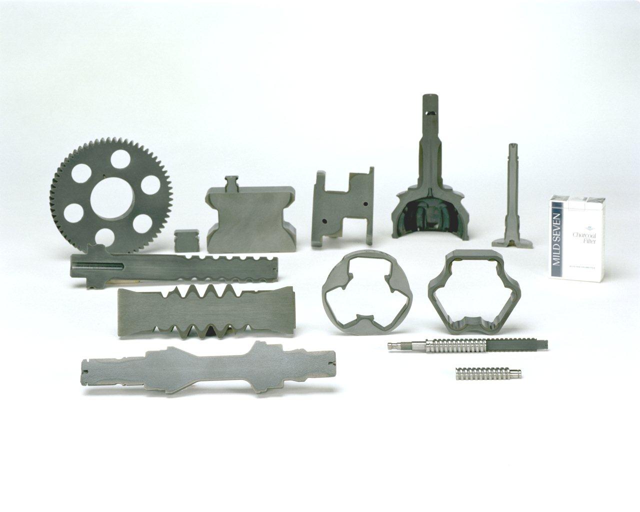
The photo shows cut samples of various machinery parts hardened
by our induction hardening machine.
The gray area of the cross section is the hardened casing.
As seen in comparison with the pictured cigarette box, the parts
are surprisingly small and the hardened areas are complexly shaped.
At Fuji Denshi, we apply our induction heating technology to meet
our customer's heat treat needs by supplying machines or providing
in-house job heat treat.
One of our specialties is heat treatment of large workpieces such as
construction machinery slewing bearing and machine tool beds and columns.
~Induction Hardening Cut Sample IH Heat Treat Automobile Parts
Production Machinery Parts~
The photo shows the hardening station of our horizontal hardening
and reheating machine for construction equipment shafts.
This machine automatically hardens mutiple types of shafts.
In the majority of our scan hardening machines, the workpiece is kept
stationary while the coil and power transformer unit moves,
a design technologically superior in general.
However, the shafts treated by this machine are relatively short.
To minimized cycle time, a horizontal scan design was chosen
with the focus on the loading/unloading speed of the shafts.
The workpiece is loaded horizontally by robot, then rolls along
the guide rail to the receive jig. After hardening, the workpiece
rolls along the unloading guide rail to the unloading station.
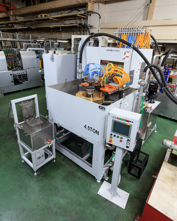
This is our induction hardening machine for idlers and track rollers used
in the continuous track of agricultural machinery such as combines.
Our specialized semi-open coil heats the rotating workpiece while the
inner surface is quenched by quenching water sprayed from the jigs.
While the varying material content of cast iron products such as this idler
make hardening difficult, we were able to achieve stable hardening through
detailed coil design and extensive trial and error calibration.
The inner surface quenching helps to prevent cracking and ensure
quality hardening.
~Induction Hardening Cracking Idler Roller Agricultural Machinery
IH Heat Treat~


