Language: 日本語 | English
Language: 日本語 | English
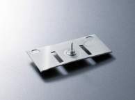
High-precision and complex-shape processing of spring materials (SUS304, SUS631, beryllium, phosphor bronze, etc.)
We offer a comprehensive service, from considering shapes with 3-D diagrams to examining and proposing materials,
plate thickness and various processing methods, followed by testing, evaluation, progressive mold manufacturing and mass production.
We provide 100% support to speed up development for our customers.

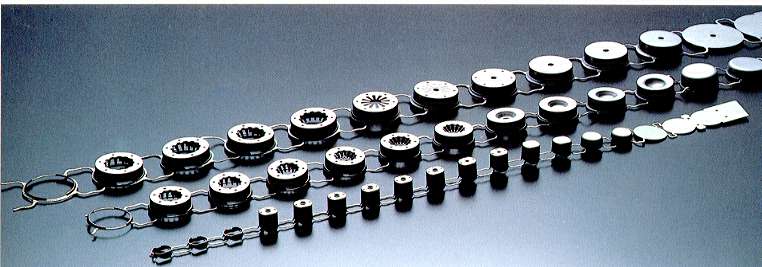
Forging is a process that makes three-dimentional objects out of materials by crushing, exciting and other deforming procedures.
Various shapes are possible. Consult with us.
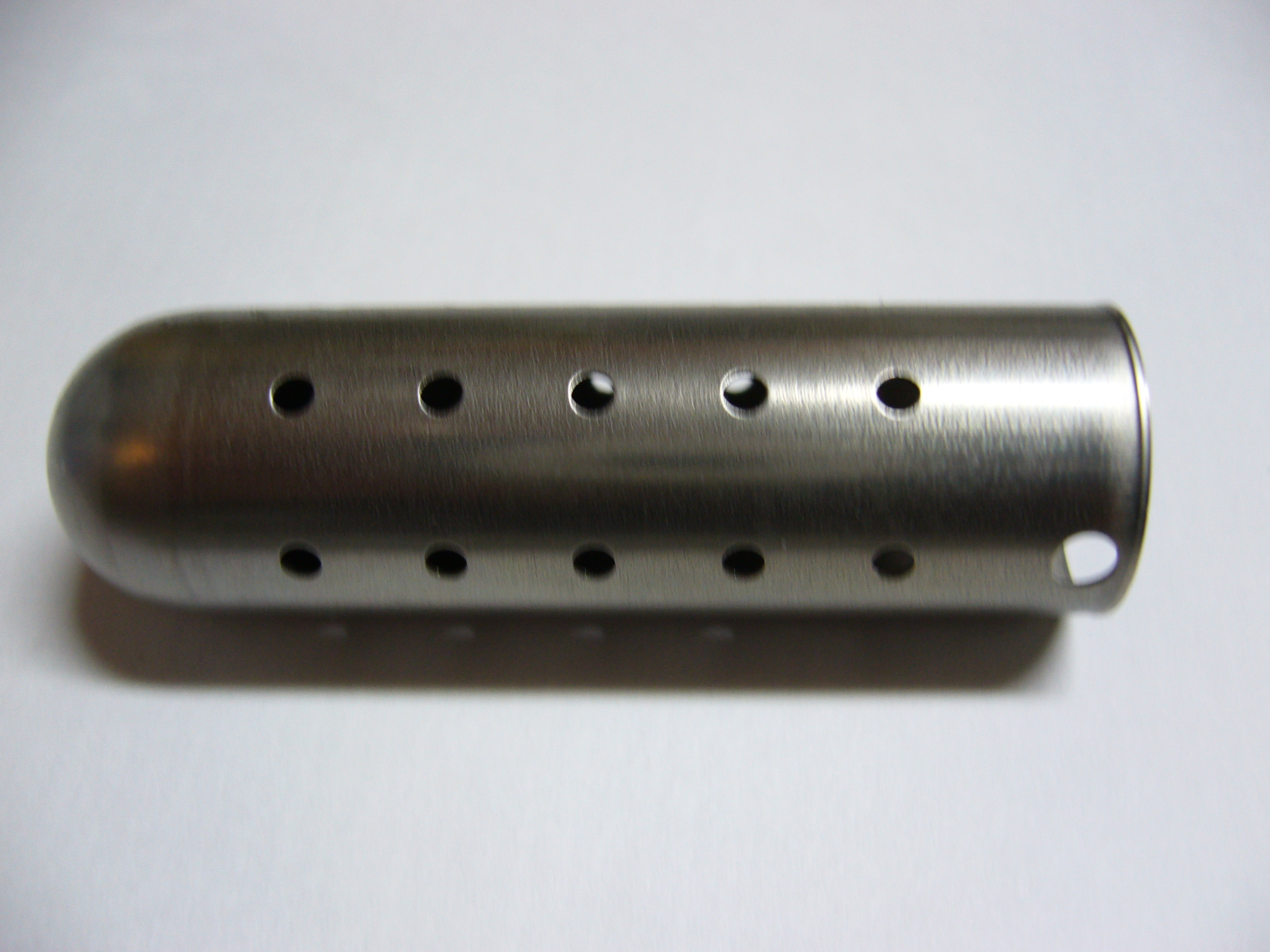
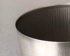
A stainless steel part manufactured using deep drawing method.
The deep drawing process is performed using a transfer press, followed by a single-stage process to create 33 piercing holes.
Approximate dimensions:
Outer diameter: φ16mm
Total length: 54mm
Hole sizes: φ2mm × 31 holes, φ3mm × 2 holes
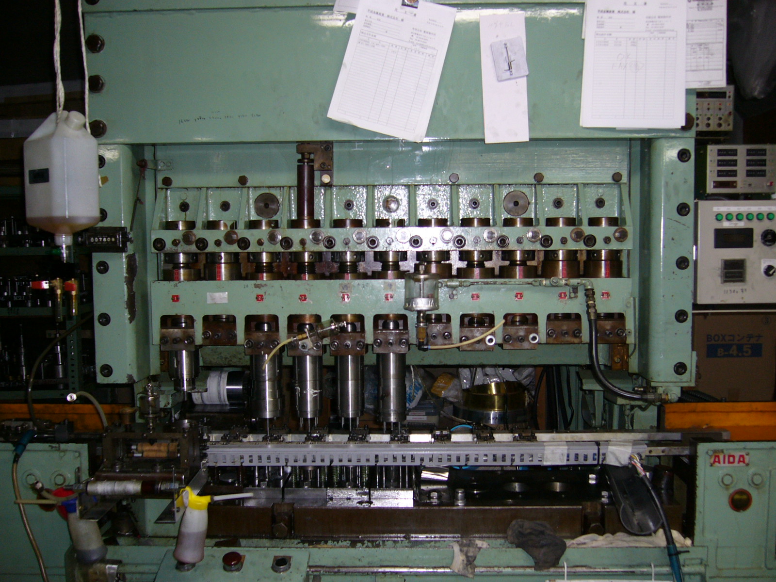
A 30-ton transfer press used for multi-stage deep drawing of stainless steel.

The Nisshin Sine Bar Chuck is a long-selling, best-selling tiltable chuck with a built-in sine bar, with nearly 30,000 units shipped to date.
Developed by our company—a precision press die manufacturer with over 60 years of history—this in-house product was originally created to dramatically streamline our own grinding process. We now offer it for sale to other metalworking and press processing companies.
We recommend using it in combination with small surface grinders from manufacturers such as Okamoto Machine Tool, Giken, Mitsui High-tec, Kuroda Seiko, and NIKKO.
For over 40 years since its release, each unit has been carefully handcrafted by skilled artisans using traditional methods. While this results in a higher price compared to competing products, it offers distinct advantages over later-developed similar sine bar chucks:
Precision and Durability:
The chuck uses a disc brake-like mechanism to secure the半月板 (half-moon plate) fixed to the spindle, ensuring a light clamping feel and precise spindle stopping. There is no loss of accuracy due to aging.
Enhanced Heat Dissipation
Unlike competing products that use simple resin-based fixes for the electromagnetic chuck electrodes, we use traditional soldering, which allows faster heat dissipation during machining.
Thanks to these overwhelming strengths, the Nisshin Sine Bar Chuck has earned a dedicated fan base among professionals who demand the highest precision and reliability.
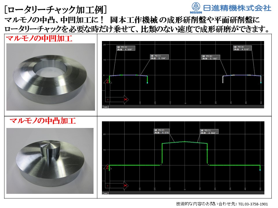
For customers struggling with convex/concave round workpieces or micron-level precision grinding, the Nisshin Rotary Chuck is the ultimate solution. This high-precision rotating electromagnetic chuck is designed to enhance grinding efficiency and accuracy.
Developed by our company—a precision press die manufacturer with over 60 years of history—this in-house product was originally created to dramatically streamline our own grinding process. Now, we offer it for sale to fellow metalworking and press processing companies.
Simple & Efficient Add-On
Attaches and detaches easily onto the chuck surface of your existing sine bar chuck or tiltable chuck in small profile grinders or surface grinders.
Perfect for low-volume, high-mix grinding operations, providing flexibility and efficiency.
Proven Applications
Silicon wafer sub-micron grinding
Reduced grinding time for ultra-hard components
The Nisshin Rotary Chuck is a game-changer for precision grinding, helping manufacturers achieve higher accuracy and efficiency with minimal setup effort.

Unlike conventional pipe benders that require fixed-radius dies, our CNC Freeform Pipe Bender allows full control over bend radius and angle through programmed processing. This innovative bending system eliminates the need for frequent die changes and enables highly complex bending operations.
Capabilities Beyond Conventional Pipe Bending
With our system, the following bending operations—previously impossible with traditional pipe benders—are now achievable:
Large-radius bends on the scale of several meters (large R bends)
Continuous variable-radius bends (compound R / progressive R) without intermediate straight sections
3D freeform curves by adjusting the axis angle of compound/progressive bends
Bend angles exceeding 180°
Multiple bend radii in a single continuous process—eliminating the need to change bending dies
Seamless 3D Data Integration
If you provide the 3D centerline data of your pipe (designed with straight and arc segments), we can instantly convert it into our proprietary CNC format using our data converter. This allows for rapid prototyping, much like a 3D printer for pipe bending.
Example Processing Program:
D=42.7
L=120 FF=25.00 FE=25.00
R=100.00 T=90.00 P=0.00 FE=25.00 FF=25.00
R=225.00 T=180.00 P=90.00 FE=25.00 FF=25.00
R=100.00 T=90.00 P=0.00 FE=25.00 FF=25.00
L=120 FF=25.00 FE=25.00
Parameter Definitions:
D = Pipe outer diameter (mm)
L = Length of straight section (mm)
R = Bend radius (mm)
T = Bend angle (°)
P = Axis angle at the connection between different R bends (°)
FF / FE = Relative speed of movement along the XY axis (relative to pipe feed speed)
Production & Custom Processing Available
We offer both small-lot prototype processing and full-scale production using our in-house CNC freeform pipe bending systems.
For inquiries, please prepare your drawings or specific bending challenges, and feel free to contact us!
We offer VA (Value Analysis) proposals to significantly reduce costs by integrating pin forming within progressive press molds and converting conventionally machined components into press-processed parts.
If it involves progressive deep drawing, we are ready to meet your needs.
With over 60 years of experience, our company—once recognized as one of the three major players in this field—has built its core business around precision progressive deep drawing molds, leveraging decades of expertise.
We offer a vertically integrated solution through Nissin Precision Machines Co., Ltd and its group companies, addressing various challenges faced by our customers with:
1. Micron-level precision machining of mold components using the latest NC machine tools
2. Design, development, and manufacturing of progressive and deep drawing precision press molds
3. Press stamping services at our two domestic factories and four overseas facilities
Our comprehensive in-house capabilities ensure high precision, efficiency, and reliability in precision deep drawing press processing.
Using SUS material, plate thickness range is 0.1–1.5mm.
After deep drawing, burr trimming (チリ切り) is used for product cutting.
Product cutting minimizes protrusion on the outer periphery and inner edge R, while reducing burr generation.
【Product Details】
Material: SUS
Plate Thickness: 0.2mm
Industry: Automotive
Processing Method: Progressive Press Die
Contact Information
Nissin Precision Machines Co., Ltd. – Head Office
〒146-0095, 2-29-21 Tamagawa, Ota-ku, Tokyo 146-0095, Japan
📞 Tel: +81-3-3758-1901
📧 E-mail: gn_info@nissin-precision.com
Contact Person: F.N
We use materials such as SUS, SPC, and SEC.
This is a method of cutting the end portion after forming the deep drawn shape, allowing cutting not only on the skirt section of the drawn part but also on the top surface of the drawn section.
【Product Details】
Material: SUS, SPC, SEC
Plate Thickness: 0.2–1.0mm
Industry: Automotive
Processing Method: Progressive Press Die
Contact Information
Nissin Precision Machines Co., Ltd. – Head Office
〒146-0095, 2-29-21 Tamagawa, Ota-ku, Tokyo 146-0095, Japan
📞 Tel: +81-3-3758-1901
📧 E-mail: gn_info@nissin-precision.com
Contact Person: F.N
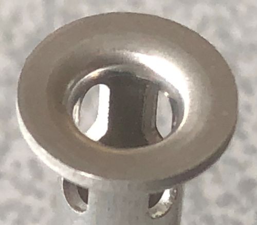
This is a method that uses a 360° cam to perform side piercing within the progressive die immediately after deep drawing for SUS, steel, and aluminum materials.
Not only uniform 90° side piercing on the outer periphery of the drawn part, but also side piercing at arbitrary angles such as 45° or 135° in the feed direction is possible, flexibly meeting user needs through stripper-integrated cams.
Applications are diverse, including automotive fuel injectors and insert fittings serving as anchors, etc.
【Product Details】
Material:Aluminum
Plate Thickness: 1.0mm and above
Industry: Automotive
Processing Method: Progressive Press Die
Contact Information
Nissin Precision Machines Co., Ltd. – Head Office
〒146-0095, 2-29-21 Tamagawa, Ota-ku, Tokyo 146-0095, Japan
📞 Tel: +81-3-3758-1901
📧 E-mail: gn_info@nissin-precision.com
Contact Person: F.N
We introduce our deep drawing die technology combined with forging bead processing.
This process applies bead forming to products after deep drawing. We work with SPC steel and aluminum (AL) materials.
At Nissin Precision, integrated progressive stamping + forging
multi-stage processing is available, enabling efficient and stable production within a single die system.
By incorporating forging beads after deep drawing, product rigidity and dimensional stability are improved while maintaining high production efficiency.
【Product Specifications】
Material: SPC steel
Thickness: 1.0 mm
Industry: Automotive
Processing Method: Progressive press die
For inquiries regarding deep drawing dies or multi-stage press processing, please feel free to contact us.
Contact Information
Nissin Precision Machines Co., Ltd. – Head Office
〒146-0095, 2-29-21 Tamagawa, Ota-ku, Tokyo 146-0095, Japan
TEL: +81-3-3758-1901
E-mail: gn_info@nissin-precision.com
Contact Person: F.N
We process SUS (stainless steel), SPC steel, and SEC steel materials.
The curling process is performed using a progressive die system, enabling stable forming and efficient mass production. We propose manufacturing methods designed with material yield optimization in mind, helping to reduce scrap while maintaining product strength and dimensional accuracy.
【Product Specifications】
Material: SUS, SPC, SEC
Thickness: 1.0 mm
Industry: Automotive
Processing Method: Progressive press die
Contact Information
Nissin Precision Machines Co., Ltd. – Head Office
〒146-0095, 2-29-21 Tamagawa, Ota-ku, Tokyo 146-0095, Japan
TEL: +81-3-3758-1901
E-mail: gn_info@nissin-precision.com
Contact Person: F.N

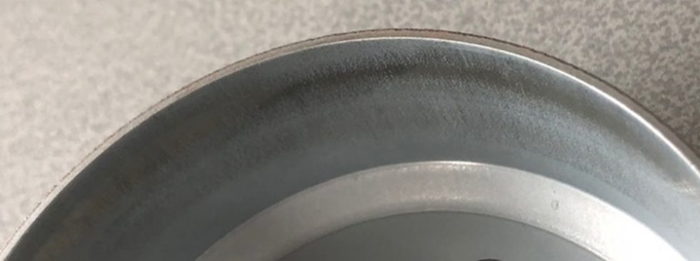
We support a wide range of materials including steel, stainless steel, aluminum, and copper.
We have extensive experience in high-difficulty deep drawing (e.g., square drawing and multi-stage drawing in SUS and aluminum materials. In SUS deep drawing, targeting zero roundness deviation, zero coaxiality error, and zero wall thickness variation, etc.).
【Product Details】
Material: SUS
Thickness: 0.1mm~1.0mm (Please consult us)
Industry: Automotive, Industrial Machinery, Home Appliances
Processing Method: Progressive press die, Transfer die, Single-stage die,
The photo shows a process conversion from bulge forming.
Contact Information
Nissin Precision Machines Co., Ltd. Head Office
〒146-0095, 2-29-21 Tamagawa, Ota-ku, Tokyo, Japan
TEL: 03-3758-1901
E-mail: gn_info@nissin-precision.com
Person in charge: F.N
Nissin Precision Machines Co., Ltd. provides integrated support from prototype processing of precision press parts to die manufacturing and full-scale mass production.
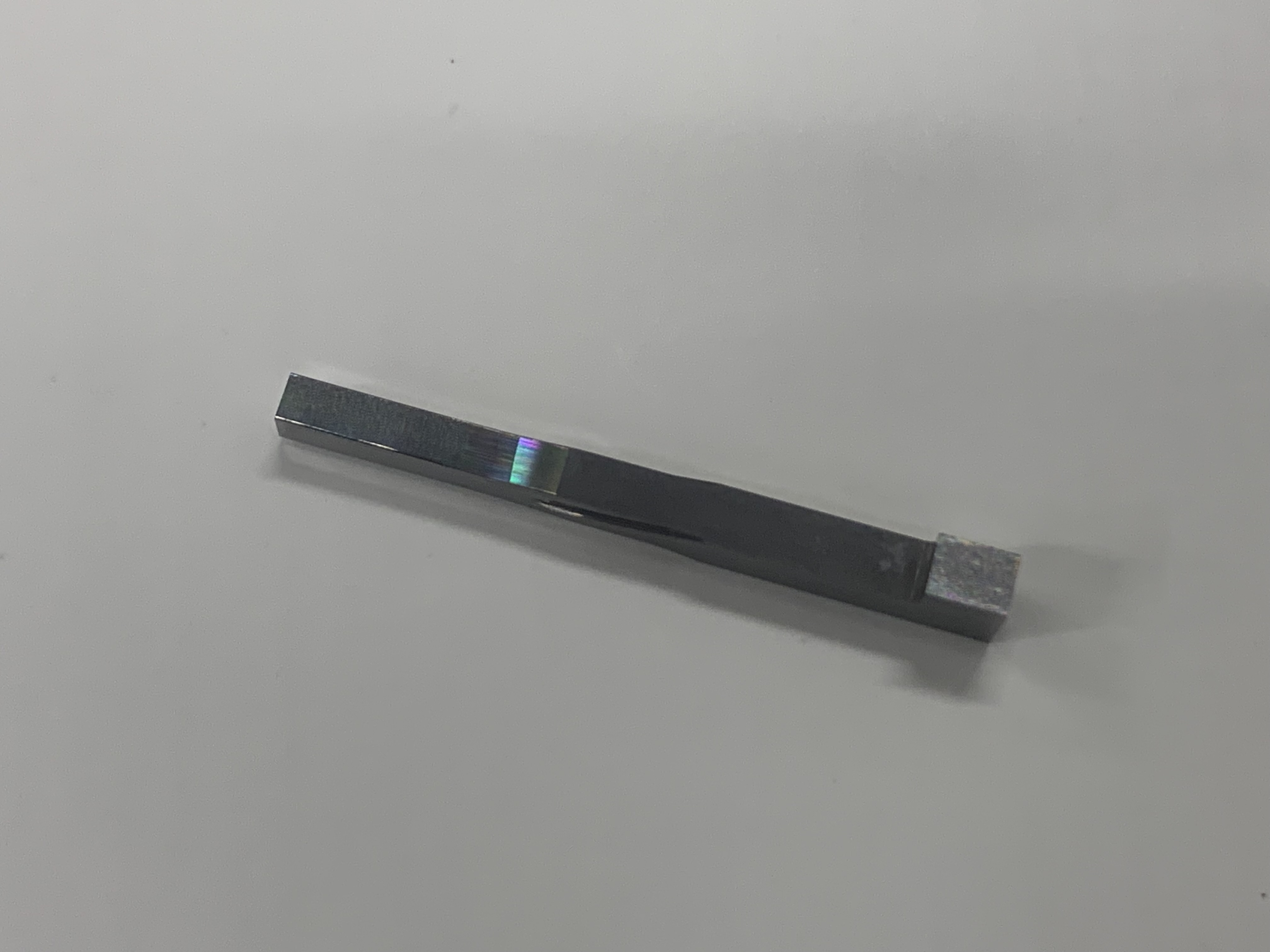
Below is an example of a punch used in dies for electronic components.
▪ Punch Specifications
- Machined Area: Cutting edge (straight square profile + corner radius R)
- Material: Cemented carbide
- Tolerance: ±0.001 mm
- Machining Equipment: Profile grinding machine
▸ About Profile Grinding
Profile grinding enables ultra-precise contour finishing of complex geometries, ensuring dimensional accuracy and edge sharpness essential for high-precision blanking applications.
▸ Digital Profile Grinding Machine DPG-150
Advanced digital profile grinding technology further enhances repeatability, measurement accuracy, and automated processing capability.
▪ Benefits of Ultra-High-Precision Finishing
- Extremely high reproducibility of press products
- Extended die service life
◎ About Nissin Precision Machines
Since its founding in 1957, Nissin Precision Machines Co., Ltd. has accumulated experience in the production of over 7,000 die sets.
The combination of proven expertise and advanced equipment may provide the solution to your precision die challenges.
Please feel free to contact us for consultation.
[Contact Information]
Nissin Precision Machines Co., Ltd. – Head Office
〒146-0095, 2-29-21 Tamagawa, Ota-ku, Tokyo 146-0095, Japan
TEL: +81-3-3758-1901
E-mail: gn.info@nissin-precision.com
Website: https://www.nissin-precision.com/products/precisiondie/
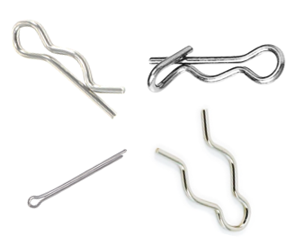
Stainless steel snap pins are widely used components in industrial equipment, known for their high durability and ease of use.
[Product Specifications]
• Materials: Compatible with SUS304, SUS316, SUS631, and other stainless steel grades
• Wire diameter range: 0.1mm to 5mm
• Corrosion resistance: Approximately 100 times more resistant than standard iron products
• Durability: Engineered for repeated use
• Feature: Easy installation and removal
[Applications]
• Automotive - Door hinges, seatbelt mechanisms
• Construction - Scaffolding fasteners, temporary structure joints
• Agriculture - Harvester part fixation, irrigation system connections
• Industrial - Conveyor belt linkages, control panel cover fasteners
• DIY - Furniture assembly, gardening tool connections
[Manufacturing Technology]
• Precise die design to mitigate springback effects
• Scheduled die maintenance program
• Strict quality control processes based on ISO 9001 standards
We specialize in precision processing of wire and strip materials, accommodating diameters from 0.1 to 5mm. Our NC-controlled manufacturing enables complex shape production.
For inquiries or custom orders, please don't hesitate to contact us.
[Company Information]
Nippon Forming Co., Ltd.
Headquarter & Main Factory: 1-23-2 Kanamachi, Katsushika-ku, Tokyo
Tsukuba Factory: 2924 Ujikai, Ishioka-shi, Ibaraki
https://www.forming.jp/eng/

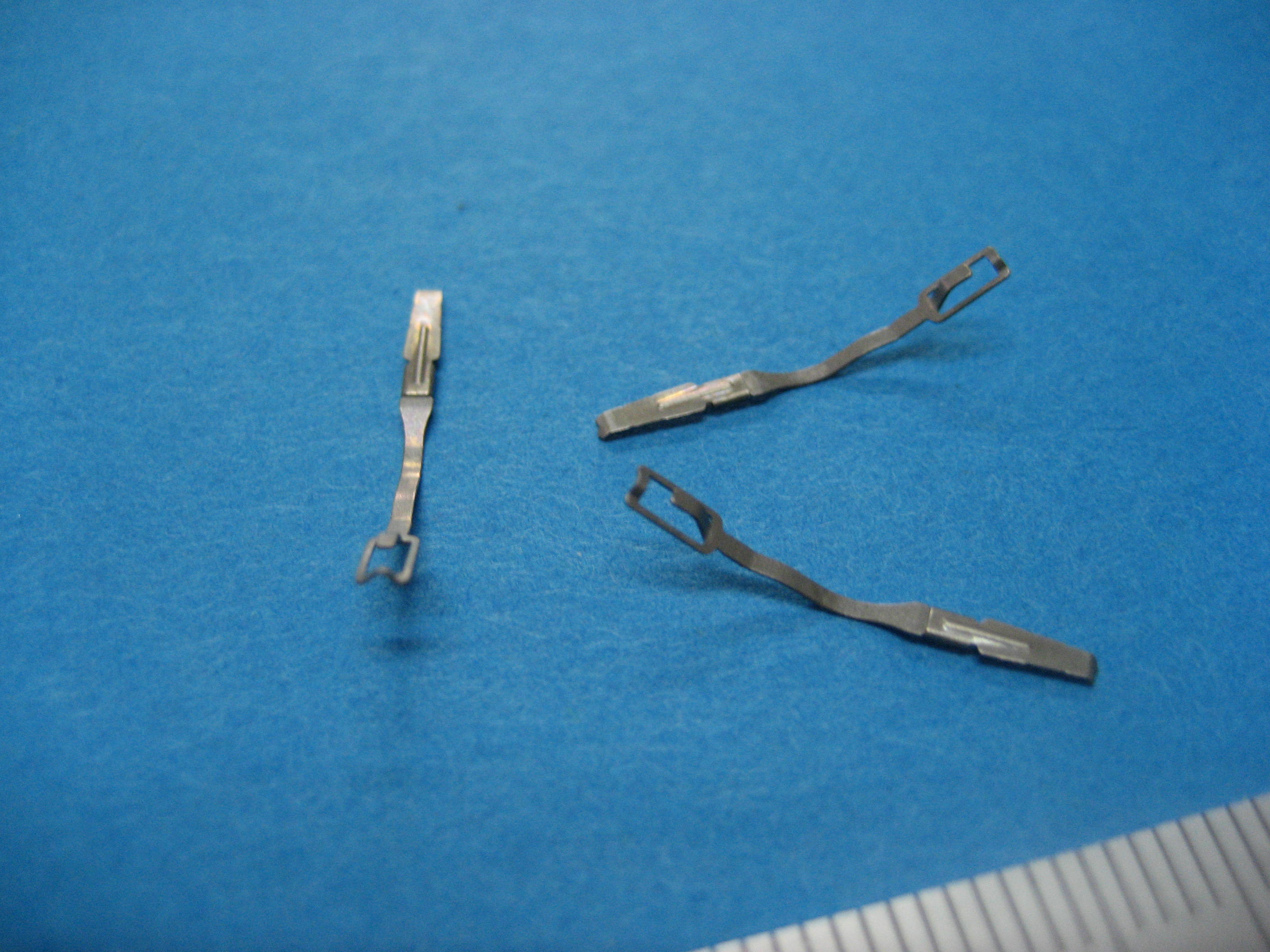
This product involves riveting four differently shaped parts within a progressive die. By performing the crimping inside the press, the process can be simplified.

[Case Study]
Sheet Metal Fabrication of Intake Manifold (Aluminum Die-Cast)
– Achieving Shorter Prototype Lead Time and Cost Reduction in Mass Production –
► Recognizing the Challenges
In the 1990s, aluminum die-casting was the dominant manufacturing method for intake manifolds in the automotive industry. However, rising raw material costs and increased manufacturing expenses due to multi-cylinder engine designs led many parts manufacturers to seek alternative production methods.
Key challenges during the prototyping phase included:
・High cost of mold production
・Lengthy prototype lead times
・Limited flexibility in design modifications
・High costs for small-batch production
►Technical Approach
Our proposed sheet metal fabrication method offers a revolutionary approach that significantly reduces manufacturing costs compared to traditional aluminum die-casting.
Key technical points include:
・Material Selection: SPHC (hot-rolled steel plate) and STKM (carbon steel mechanical tubing)
・Optimized Design: Strength analysis and weight reduction using 3D CAD
・Manufacturing Process: Combination of press forming, laser processing, and welding technology
・Quality Assurance: High-precision dimensional verification using 3D measuring instruments
►Detailed Solutions
The sheet metal fabrication of the intake manifold was developed through the following phases:
1. Design Phase
・3D modeling using CAD
・Design of press molds and jigs for laser processing and welded assembly
・Development of DNC machining programs based on 3D models
2. Prototype Phase
・Mold and jig processing using DNC machining
・High-precision machining with a 5-axis laser cutter
・Precision welding by skilled technicians
3. Validation Phase
・Dimensional verification using 3D measuring instruments
・Performance evaluation through actual vehicle installation tests, followed by design optimization
・Durability testing and feedback-driven design improvements
►Implementation Benefits
This development project achieved the following results:
✔ Manufacturing Cost: Reduced by 40% compared to conventional methods
✔ Development Period: Prototype lead time shortened by 50%
✔ Weight Reduction: 20% lighter than conventional
✔ Design Flexibility: Significantly improved
These achievements were made possible by over 50 years of prototype development experience and a team of 160 skilled engineers. We continue to apply this technology to the sheet metal fabrication of various automotive components.
►Future Prospects
In recent years, some intake manifolds have transitioned to resin materials. However, the optimal manufacturing method depends on the required component characteristics and operating environment.
We propose the best manufacturing solutions, including sheet metal fabrication and hybrid approaches, tailored to each customer’s needs.
►Conclusion
Sheet metal fabrication of intake manifolds is a highly effective solution that achieves both cost reduction and weight savings.
For more details, please download our technical documents from the link below and discuss potential applications with your development team.
[Company Profile]
Company Name: Timec Co., Ltd.
Address: 197-1 Nishigori, Soja City, Okayama, 719-1164, Japan
TEL: +81-866-93-1269
FAX: +81-866-93-2540
Corporate Website: https://timec.co.jp/
🔹 Download Technical Documents:
https://ja.nc-net.or.jp/company/22325/dl/catalog/207206
🔹 Technical Consultation & Quotation Requests:
https://ja.nc-net.or.jp/company/22325/inquiry/
🔹 Related URL: https://timec.co.jp/

Oil Pan Prototyping and Development – A Critical Component for Engine & Transmission Performance
In the automotive industry, the oil pan plays a crucial role in ensuring the performance and reliability of engines and transmissions. This guide, based on over 50 years of experience in prototype development, addresses the challenges and solutions in oil pan manufacturing.
Key Challenges in Oil Pan Development
Currently, the automotive industry faces several challenges in oil pan production:
1. Strict control over material thickness reduction
2. High-precision surface quality for mounting areas
3. Reduction of lead time from prototyping to mass production
4. Maintaining cost competitiveness
Particularly in deep drawing press forming of oil pans using mild steel sheets, precise control over material thickness reduction is essential.
Customer Feedback:
Since these parts are used around the engine and transmission, oil leakage is absolutely unacceptable.
Technical Solutions
To address these challenges, we implement the following technological approaches:
1. Deep Drawing and Press Forming Simulation
Pre-evaluation using JSTAMP software
Prediction and optimization of material thickness reduction rates
Prevention of forming defects in advance
High-Precision Die Design & Manufacturing
2. High-Precision Die Design and Manufacturing
Precision design using 3D CAD
Uniform surface pressure distribution with unique die structure
Finishing by skilled technicians
3. Quality Assurance System
100% inspection with 3D measuring machines
Verification of mounting surfaces with dedicated inspection jigs
Operation of traceability system
Actual case studies have shown the following improvements:
✔ Prototyping period: Reduced by 30% compared to conventional methods
✔ Cost: Lowered by 30% compared to traditional techniques
✔ Mass production transition: Smooth and efficient ramp-up
Our expertise in deep drawing press forming, particularly in controlling material thickness reduction, is what sets us apart in manufacturing oil pans for engine and transmission components.
Founder’s Comment:
Only real technology can meet such strict requirements.
Proposal to Customers
We have even more detailed technical documents available. You can download them for free from the following URL:
https://ja.nc-net.or.jp/company/22325/dl/catalog/207206
Please feel free to contact us from the following form for technical consultations and quotation requests:
https://ja.nc-net.or.jp/company/22325/inquiry/
[Company Profile]
Company Name: Timec Co., Ltd.
Location: 197-1 Nishigori, Soja City, Okayama Prefecture 719-1164
TEL: 0866-93-1269
FAX: 0866-93-2540
Corporate Website:
https://timec.co.jp/
Related URL: https://timec.co.jp/

Industry Challenges
In manufacturing prototyping, achieving both high quality and short lead times is a significant challenge. In particular, lower arm assemblies—key automotive suspension components—require exceptional strength and precise machining accuracy. However, shortening the development period for such parts has been a persistent challenge.
Technical Solutions
By combining press forming analysis, high-output hydraulic presses, and 3D laser machining technology, we effectively address these challenges. The production of lower arm assemblies demands deep drawing techniques for enhanced strength and precision shaping using 3D laser processing.
The Importance of Lower Arm Assemblies
As a critical component in a vehicle's suspension system, the lower arm assembly connects the chassis to the wheels, directly influencing driving stability and ride comfort. This makes high strength and precise dimensional accuracy essential.
Quality Assurance through Integrated Production
✔ Design Phase: Utilizing advanced 3D-CAD systems like CATIA
✔ Processing Stage: Deep drawing with a 1,200-ton hydraulic press and high-quality welding
✔ Quality Control: High-precision inspection using large-scale 3D measurement systems
Production System for Shorter Lead Times
24/7 production system to maximize manufacturing capacity
Integrated workflow from design to inspection
Optimized welding assembly with a synchronized-axis welding system
Implementation Results
✔ Development time: Reduced by up to 50%
✔ Costs: 30% reduction compared to conventional methods
✔ Improved precision and quality stability
Customer Feedback
The prototype period was significantly reduced, accelerating our product development. The quality is also stable, and the transition to mass production is smooth.
— Development Manager, Major Automotive Manufacturer
Download Technical Documents
We have prepared detailed case studies showcasing solutions to product development challenges, including:
✔ Know-how of high-difficulty press working
✔ Process flow for achieving short lead times
✔ Details of the quality assurance system
⇒ Click here to download the document: https://ja.nc-net.or.jp/company/22325/dl/catalog/207206
◎ Company Profile
Company Name: Timec Co., Ltd.
Location: 197-1 Nishigori, Soja City, Okayama Prefecture 719-1164
TEL: 0866-93-1269
FAX: 0866-93-2540
Corporate Website:
https://timec.co.jp/
Technical Consultation/Quotation Request: https://ja.nc-net.or.jp/company/22325/inquiry/
Related URL: https://timec.co.jp/

► Industry Challenges
Are you facing challenges in the seamless transition from prototyping to mass production of seat leg parts in manufacturing?
In the automotive industry, manufacturers must balance lightweight design, high strength, cost reduction, and short lead times, which often have conflicting requirements.
Additionally, interference checks with surrounding seat components and assembly feasibility validation require precise adjustments. The quality of the prototype phase directly affects mass production efficiency.
► Our Approach to Solutions
With over 50 years of expertise in prototype development, we provide optimal solutions tailored to our customers' needs.
Our Strengths in Seat Leg Component Production:
✔ Proposals from the design stage using 3D CAD
✔ Preliminary validation with press forming simulation
✔ Comprehensive support from material selection to processing methods
✔ Ultra-short lead times enabled by 24-hour operations
We offer the following specialized services for seat leg parts:
✔ Material: SPH, STKM, and other optimal materials based on application needs
✔ Processing: Single-unit press processing and pipe processing
✔ Assembly: Integrated welding assembly and surface treatment
► Technical Features
【Equipment Capabilities】
✔ 1,200-ton large press machines for high-precision processing
✔ 3D laser processing machines for complex shapes
✔ Robotic welding systems for high-quality joining
✔ 3D measuring machines for precise quality control
【Manufacturing Process Strengths】
1. Design Support
Equipped with CATIA and multiple 3D CAD systems
Conducts interference checks with surrounding seat components
Offers design proposals optimized for assembly feasibility
2. Prototype Manufacturing
Short lead times utilizing state-of-the-art manufacturing equipment
High-precision processing by skilled technicians
Quality stabilization using custom jigs
3. Small-Lot Production
Flexible support for small-lot production after prototyping
ISO9001-certified quality control system
► Proven Benefits
Our clients have experienced the following improvements:
✔ 30% reduction in development time
✔ 25% reduction in prototyping costs
✔ Streamlined transition to mass production
✔ Significant reduction in quality defects
★ Success Story
We were looking for a manufacturing partner that could handle everything from prototyping to small-lot production of seat leg components. By working with your company, we achieved faster development and stabilized quality.
— Major Automotive Parts Manufacturer
► Delivering Even Greater Value
For a detailed technical guide, download our free materials here:
🔗 Download Technical Documents
https://ja.nc-net.or.jp/company/22325/dl/catalog/207206
For technical consultations and quotations, please use the form below:
🔗 Inquiry Form
https://ja.nc-net.or.jp/company/22325/inquiry/
【Company Information】
Timec Co., Ltd.
📍 197-1 Nishikoori, Soja City, Okayama, 719-1164, Japan
📞 TEL: 0866-93-1269
📠 FAX: 0866-93-2540
🌐 Website: https://timec.co.jp/
🔗 Related URL: https://timec.co.jp/
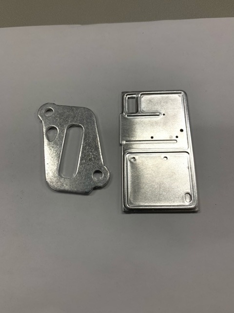
This is a processed product formed using a forging press die from sheet material.
It is manufactured using a press method with a die.
Specifications:
① Material: A1050
Base plate thickness: t1.2
Application: Automotive sensor
Dimensions: 60mm × 32mm
Tolerance: Flatness ±0.1μm, Punching tolerance ±0.1μm
② Material: A1050
Base plate thickness: t2.0
Application: Automotive sensor
Dimensions: 42mm × 30mm
Tolerance: Flatness ±0.1μm, Punching tolerance ±0.1μm
Both sides full R0.5
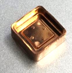
This is a forged product formed through multiple press processes from sheet material, designed with a thin outer wall and a raised center.
It is manufactured using a press method with a die.
Material: C1100
Base plate thickness: t1.6
Application: EV headlight
Dimensions: 9mm × 9mm × 4mm
Tolerances:
Flatness: ±0.01μm
Outer wall tolerance: ±0.01μm
Burr: ±0.01μm
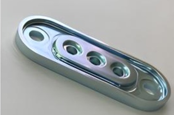
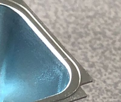
This product is formed from sheet material with protrusions and recesses on both sides, requiring high dimensional accuracy.
It is manufactured using a press method with a die.
Material: SPCC
Base plate thickness: t3.2
Application: EV compressor
Dimensions: 80mm × 30mm × 3mm
Tolerances:
Flatness: ±0.07μm
Round hole circularity: φ0.15μm
Contour accuracy: ±0.4μm
Positional accuracy: φ0.1μm
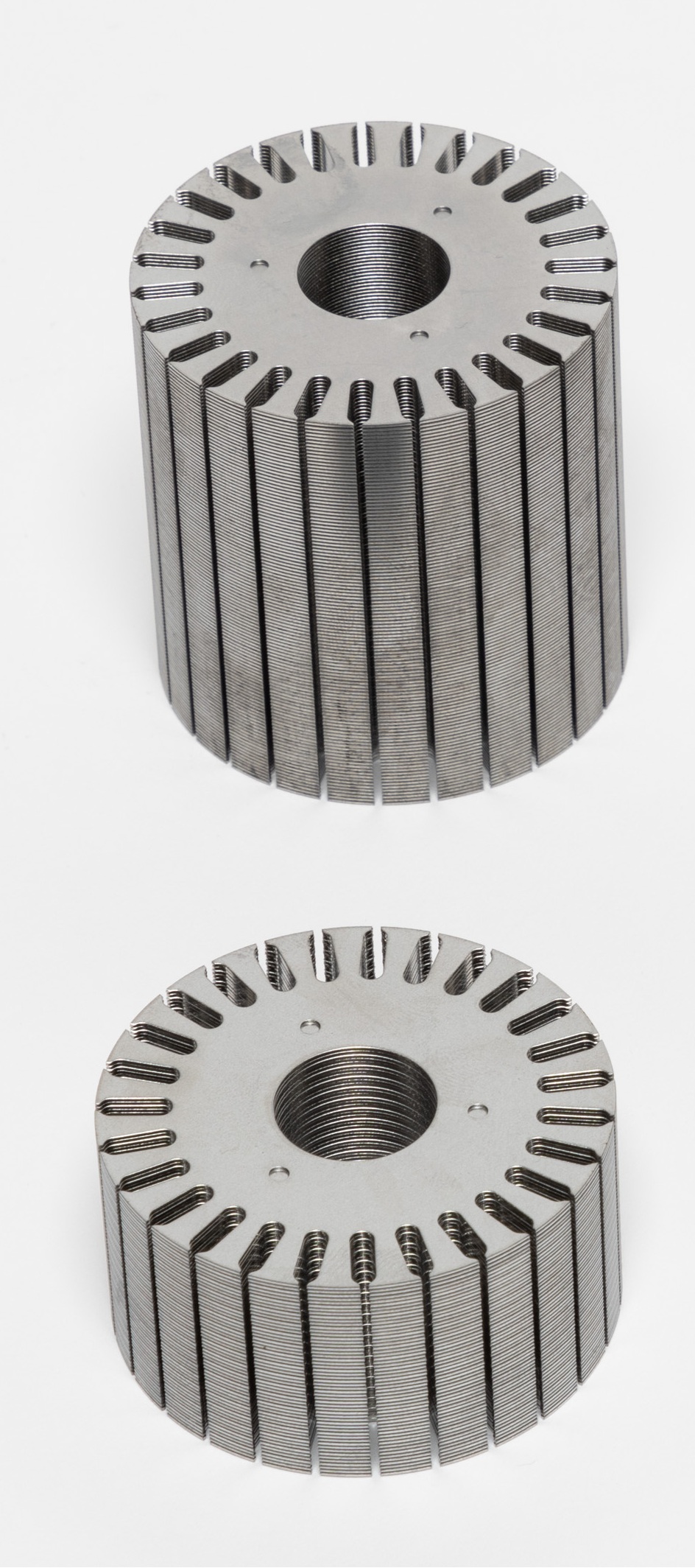
This product is a core component manufactured by laminating and caulking 0.5 mm thick steel sheets inside a die, using SPCC as the base material.
[Shape]: Cylindrical shape, φ52.8 mm in diameter and 55 mm in height
[Application]: Automotive motor
⁂ The dimensional and geometric accuracy of this product is ensured through in-process inspections and final inspections using a coordinate measuring machine (CMM) and non-contact laser measuring equipment, guaranteeing product functionality and reliability.
With many years of experience and proven technical expertise, we are committed to supporting manufacturing that closely meets our customers’ needs. Please feel free to contact us!
For inquiries, please contact us at the details below.
ꕤ︵ꕤ︵ꕤ︵ꕤ︵ꕤ︵ꕤ
Ohnuki Kogyosho Co., Ltd.
Sales & Production Control Department
Takuya Osumi / Miu Wada
📩 infoh@ohnuki.co.jp
📞 0294-53-3821
ꕤ︵ꕤ︵ꕤ︵ꕤ︵ꕤ︵ꕤ

By applying our company's shaving technology to drawing, we've achieved the creation of 2-mm plane surfaces from drawn edges.
View our company website.

This is a promotion video shows our news technology WARISAKI.
We acquired domestic patent and applied for Taiwan Patent.
How would you use this technology?
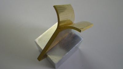
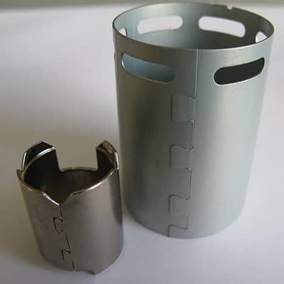
We have succeeded in splitting a plate of brass.

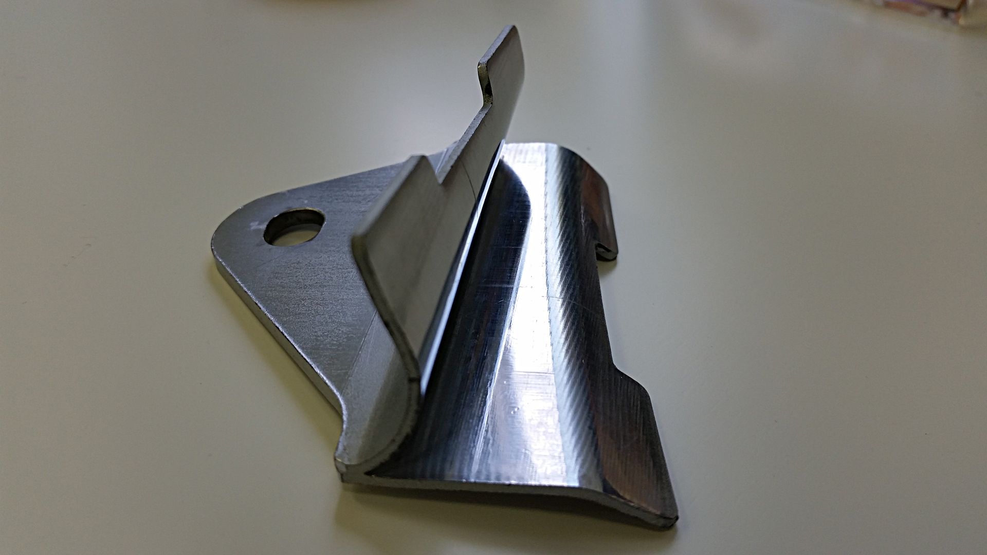
We produce T-shape bracket only by Press processes.
meterials available: Copper, Aluminum, Steel, Brass.
** the reference photo is Steel and Brass.
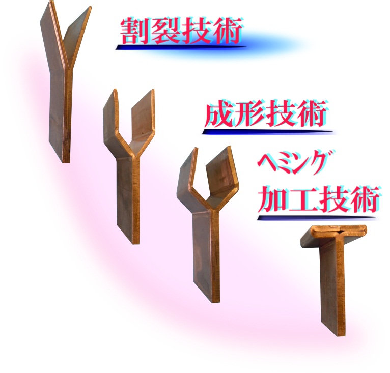
This is the world’s first technology to succeed manufacturing the product from splitting technology (Patent No. 5165806, International and Taiwan patent pending) to Heming processing in the progressive die. It achieved the shortening of the lead time and reducing the cost from the conventional construction method.
Materials: Steel, Aluminum, Copper
It has various uses
・Complex 3D shapes by splitting and hemming
・Jointing dissimilar metals
・T-shape brackets
The Splitting technologies of the titanium and the stainless steel are now on trial.
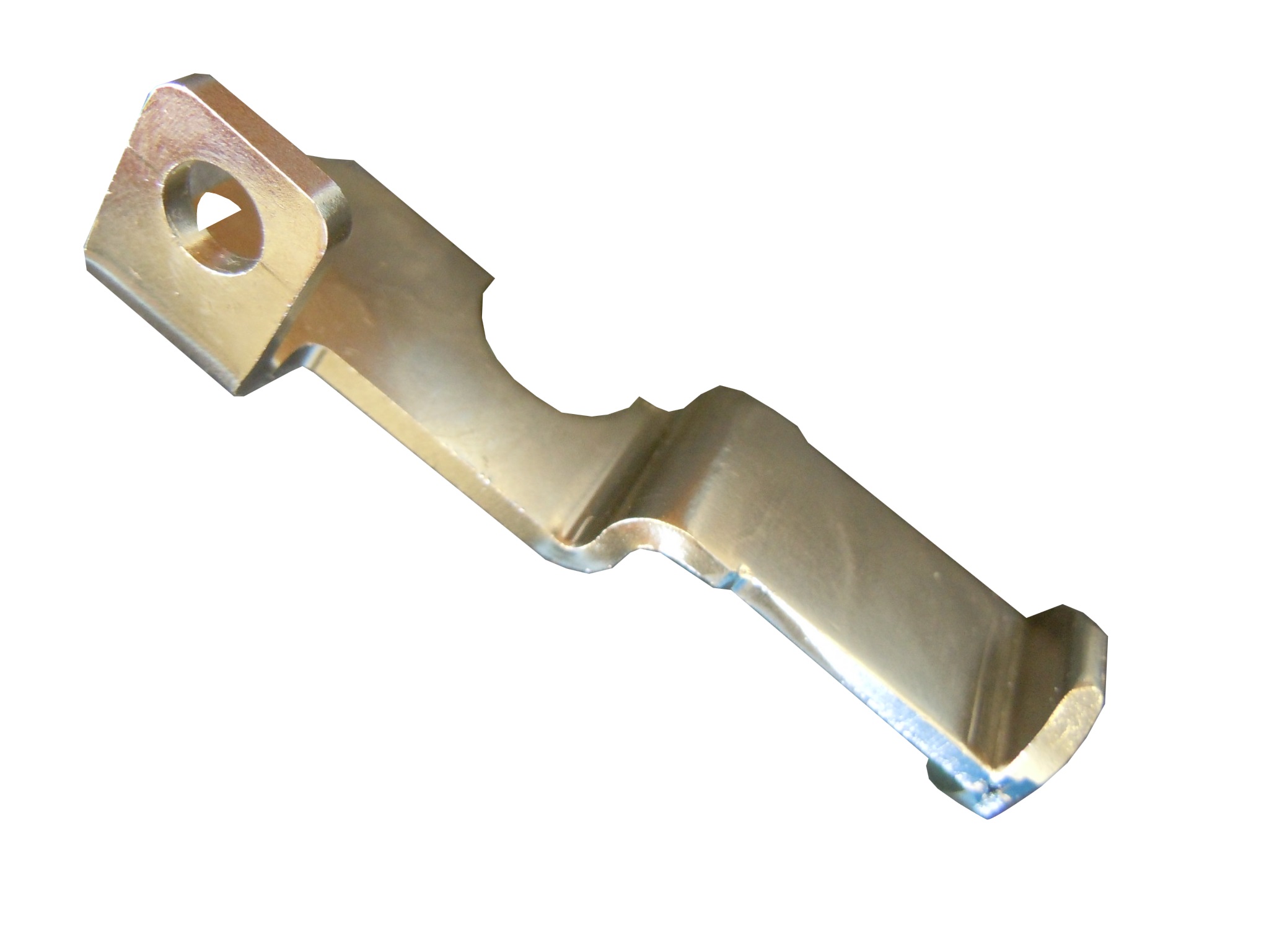
We utilized splitting (Warisaki) processing technology and succeeded to manufacture integrated cast processing products of complicated 3D shapes by the metal press.
・Shifting from previously manufacturing by welding and forging to now process by products by the metal press enabled us to
1) Reduce cost (maximum of 75%)
2) Shorten the lead time (by one quarter)
3) Greatly improve the quality stability due to no connection such as the welding construction method
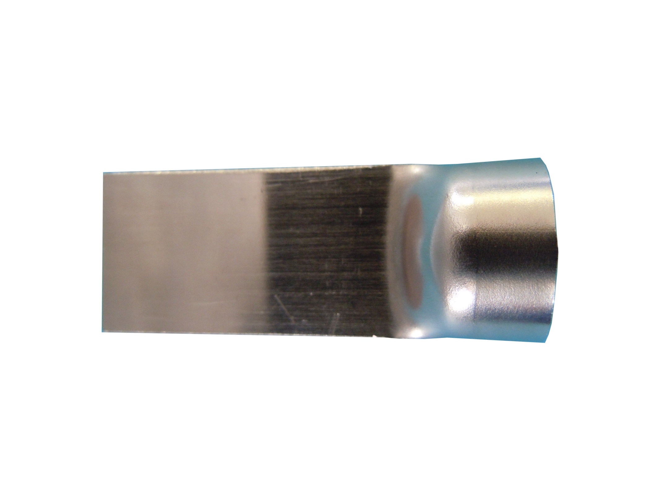
We provide a round-tip product by applying splitting (Warisaki) processing technology.
・To change the material shape from flat metal to round metal!
・To put the round shaped part to the flat metal directly!
We can cope with a specially ordered product if the diameter of the round shape is within the dimension which can be put on the press.
We constantly handle with the extending of the materials.
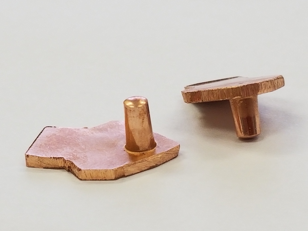
A solid projection was formed on a 1.5mm thick plate in a single press process.
A proprietary technology following Warizaki (Japanese patent obtained).
Method Name: [Turm Method] ★ Turm means tower in German ★
[Warizaki] Method
A single piece is formed from a plate (no welding, seamless structure).
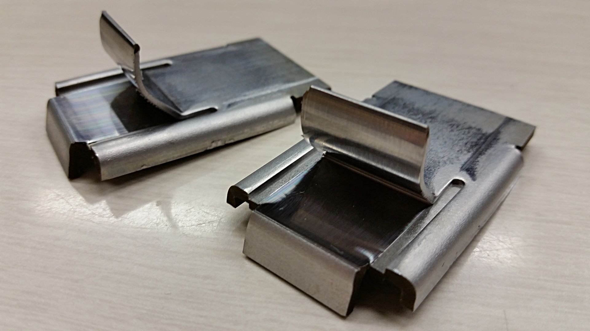
[Partial Warizaki] Method
Integrally molded piece.
The plate is drawn, and the drawn edge is split along the outer perimeter, forming a three-dimensional integrally molded piece.
ONLY ONE Processing Technology [Outer Perimeter Warizaki Method]
Draws a plate, then splits the drawn edge along the outer perimeter to achieve a three-dimensional shape.
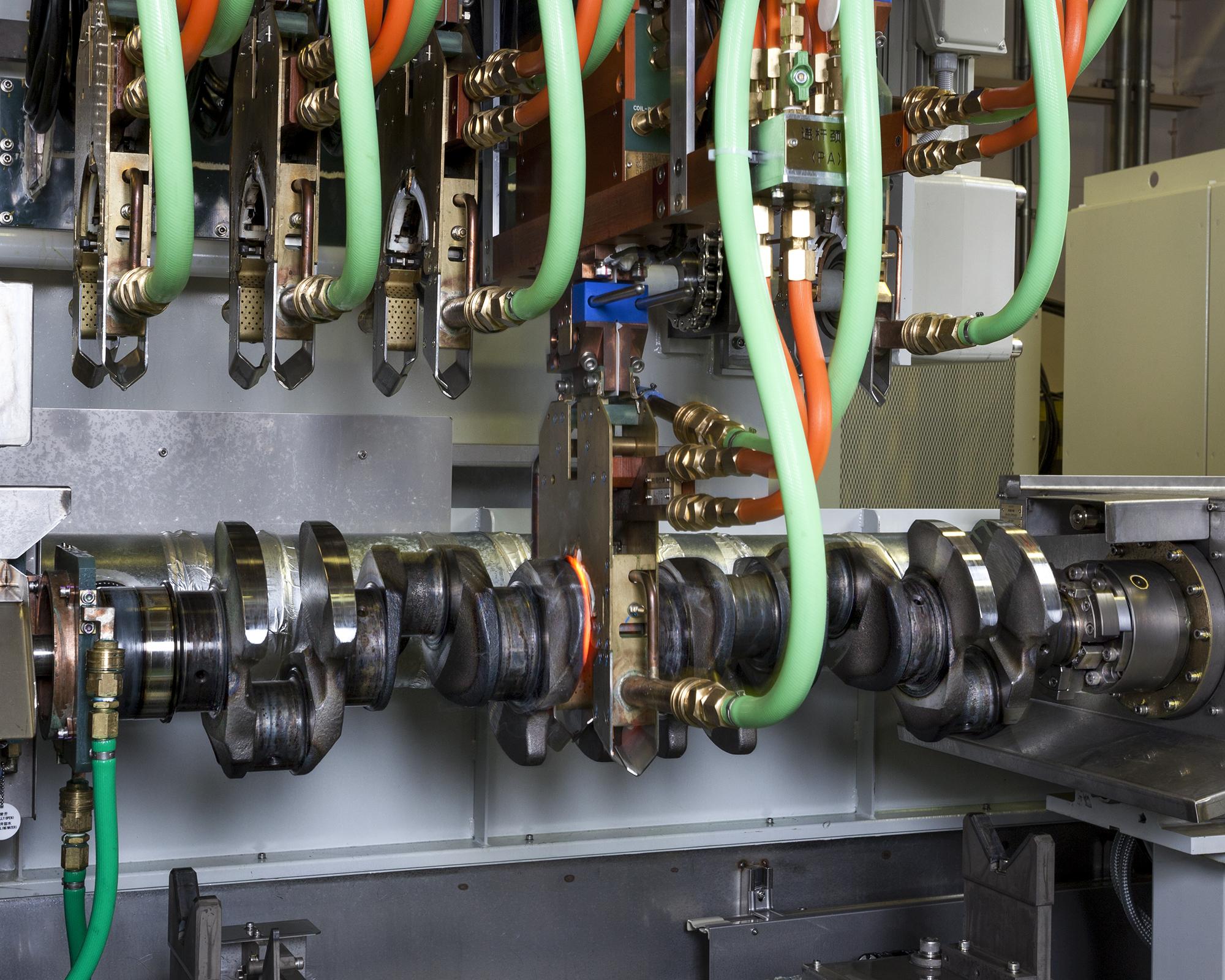
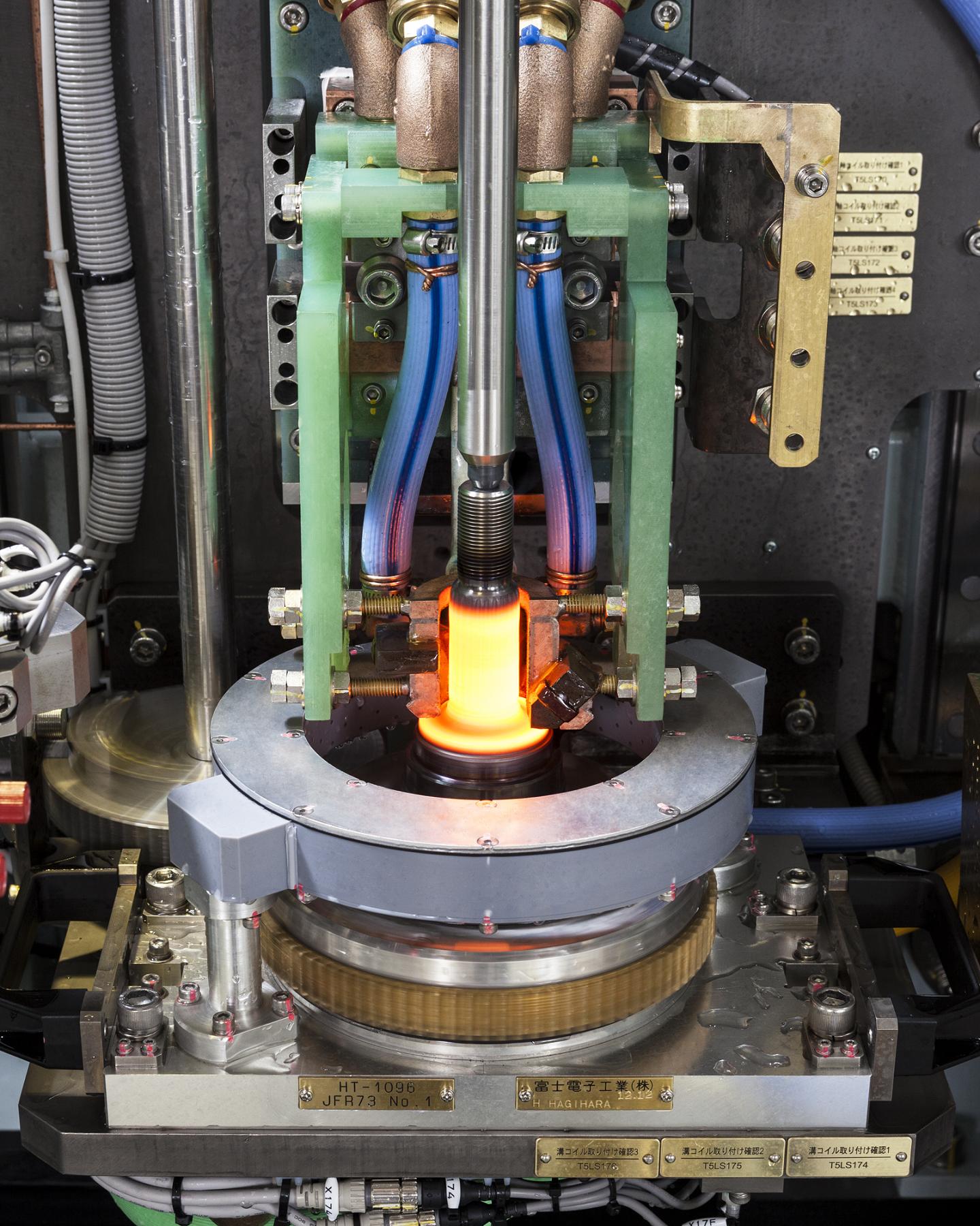
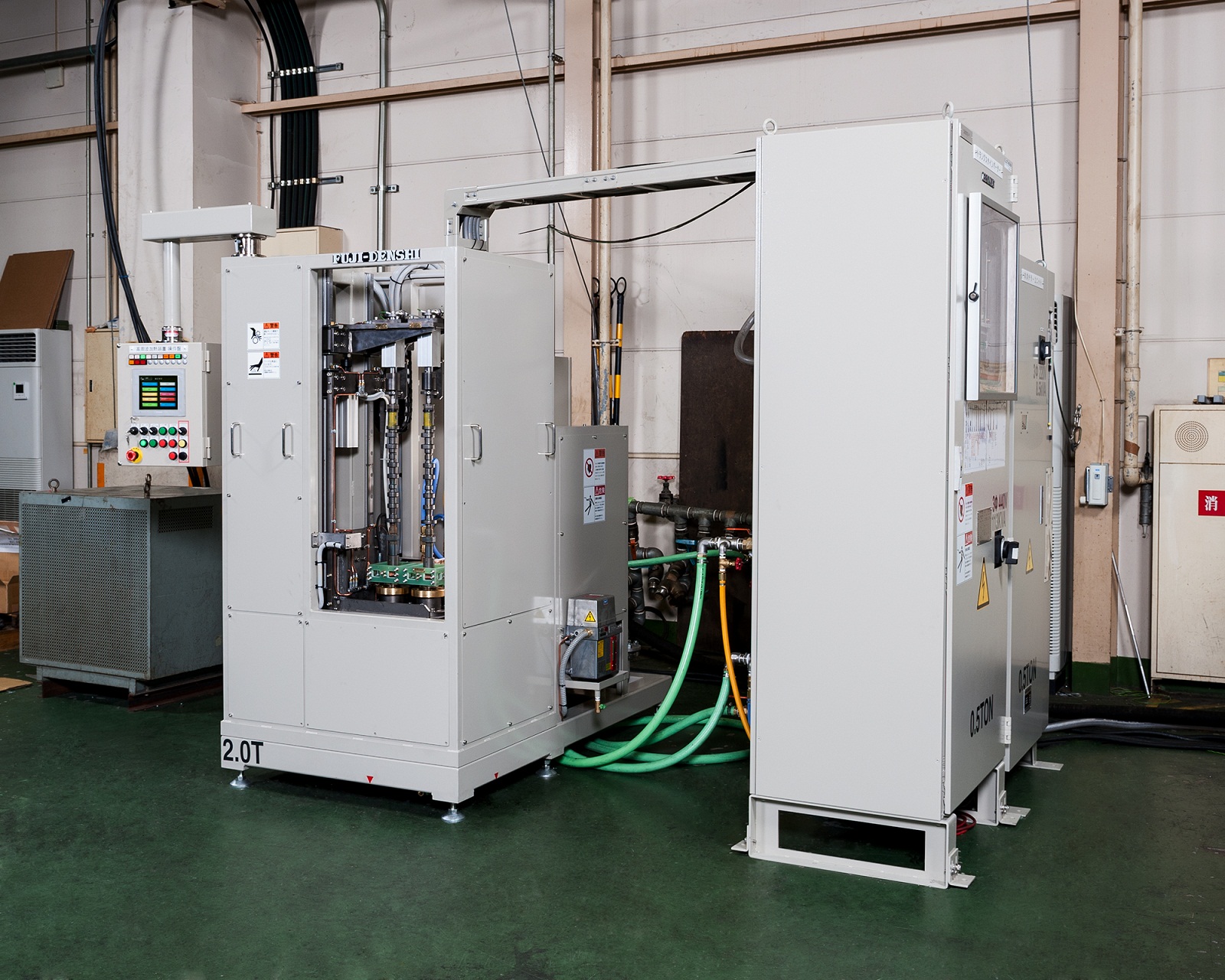
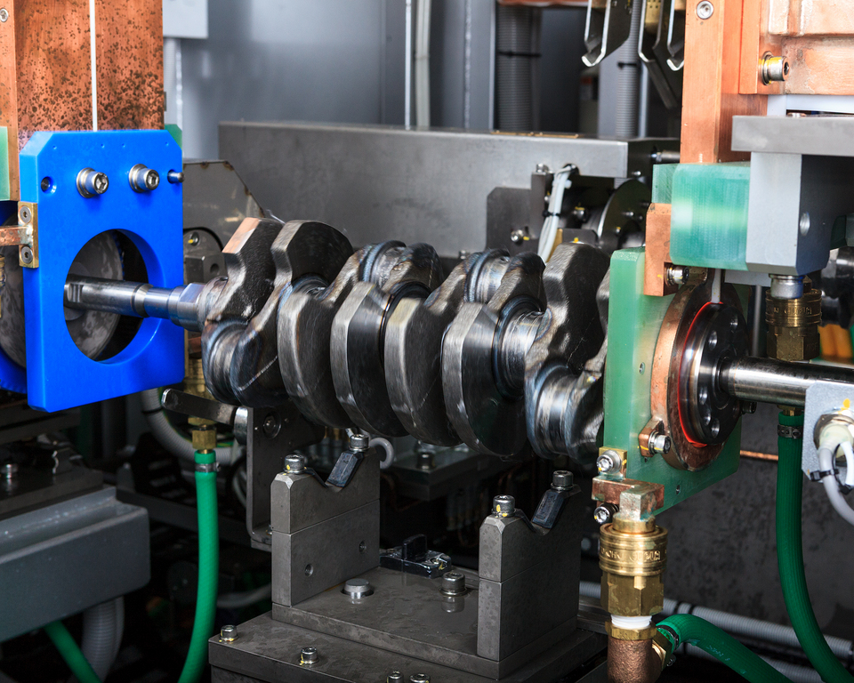
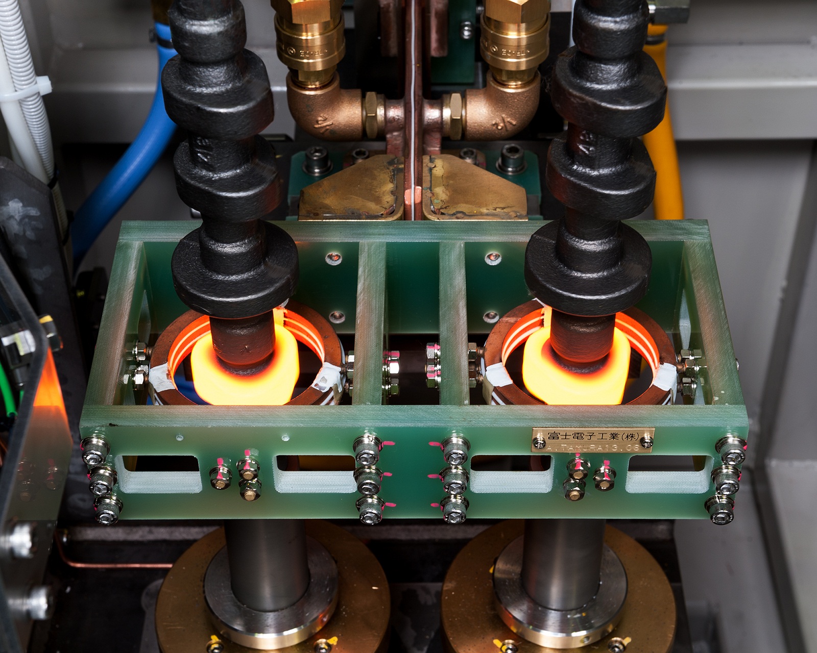
This product is a type of crankshaft quenching used in automobile engine parts.
Fuji Electronic Industry owns 80% of the share market in Japan with accumulated knowledge to challenge to new technologies.
Our crankshaft quenching is processed through a unique method called Elothrm method.
We have an established technique for the quench pattern (R quenching) which can be seen in this picture and will be glad to suggest applying to customer’s products.

The product shown in the picture is a cut sample of a small diameter precise ball screw.
The bottom (diagonally right) product has been processed using an ordinary quenching technique.
The top (center) product’s appearances are exactly as before processing.
However, inner portion is quenched completely.
As one can see, our “non-oxidation quenching” will not cause any scale as ordinary quenching.
This method requires no after treatment as shot blast.
In other words, scales and sands which can cause reduction of after treatment preciseness will not be problematic.

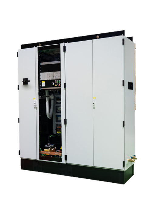
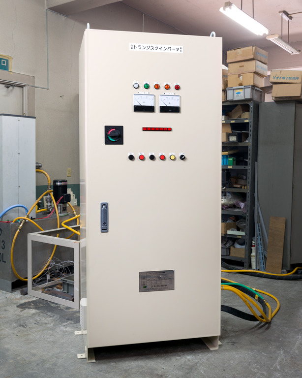
We sale high frequency induction heating machineries.
This machine will utilize the induction heating principle which has effects on improving surface hardness and improved wear resistant.
【Advantages of the Induction Heating Quenching】
・Shorter lead time → Reduced processing steps
・Efficiency → Lower electricity usage, aka energy saving
・Heat when needed → A small lot manufacturing
・Partial Quenching → Partially quench depending on the shape
・Only require electricity → Ecological (no smoke and/or gas emission)
・The product will generate heat → Heat efficient
・Easy to in-line
In addition, our manufacturing section produces products on commission.
Also gladly handle a small lot orders, complicated shapes, and/or first time quenching for the specific product.
Feel free to contact us.
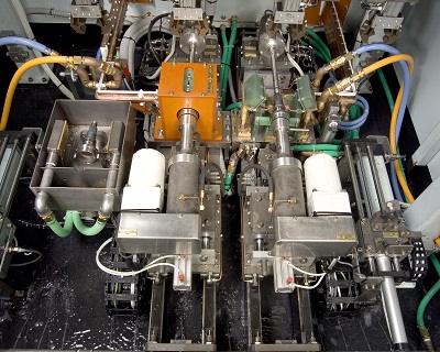
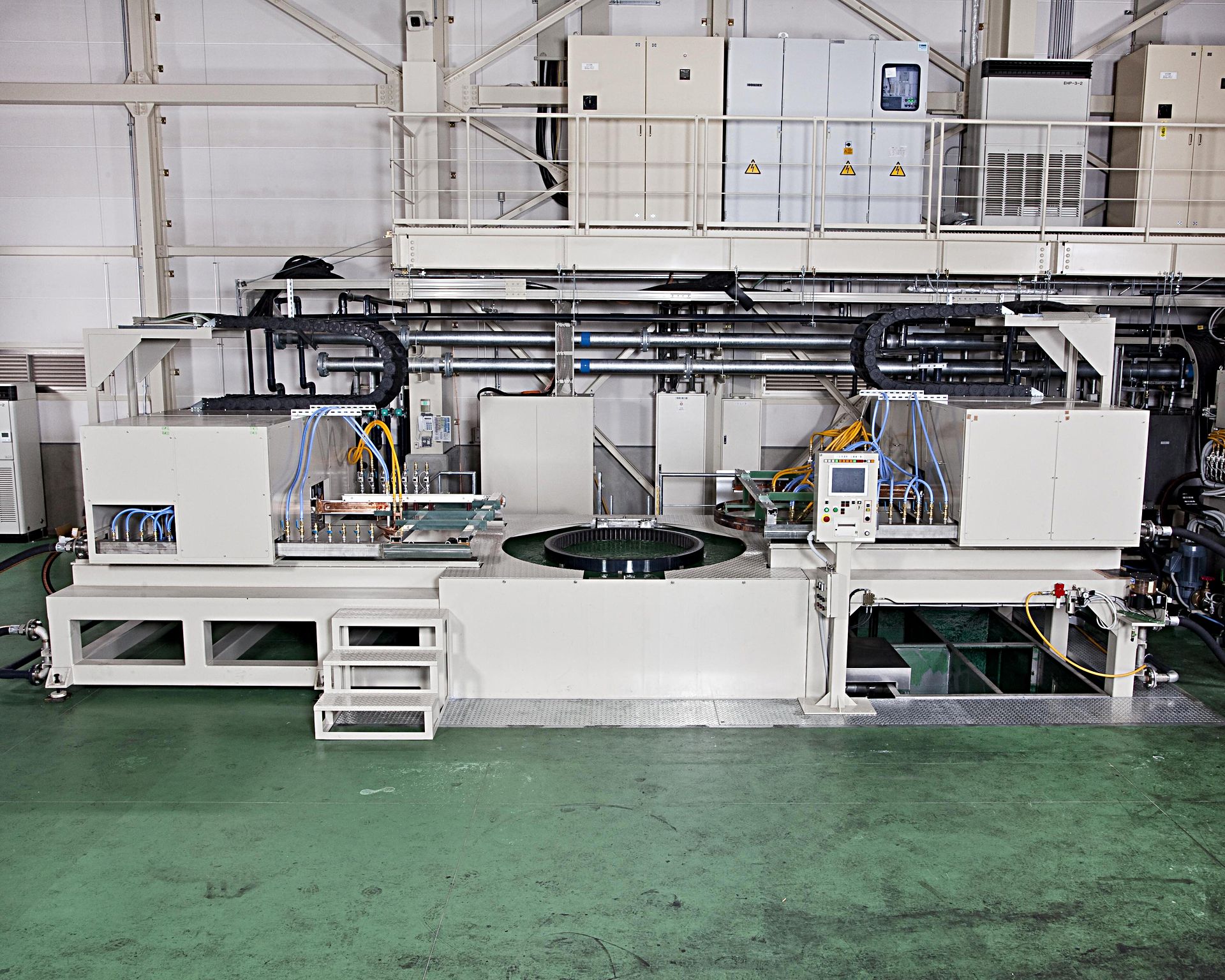
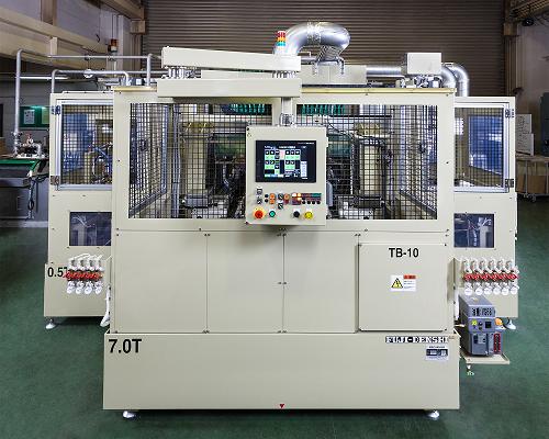
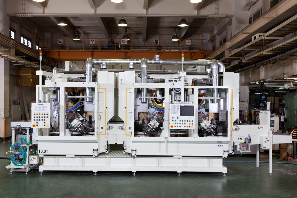
We have achieved to establish simultaneously and automatic cam quenching which can manufacture 240/h and 3600 sections resulting in overall cost reduction.
For those work which each cam and journal are placed side by side, by using our uniquely produced outlet ring, the ring will insulate any effect towards unnecessary parts.
Also, by adjusting bearing and cam, other types and shapes of camshaft can be processed.
We will gladly support prototyping, quality inspection, equipment installation, and maintenance of equipments after installation.
*Please consider us for prototyping, manufacturing by commissioning, and buying equipments.
Picture:Double Quenching. Cycle time 1:27 per 2.
Hands on and off model.
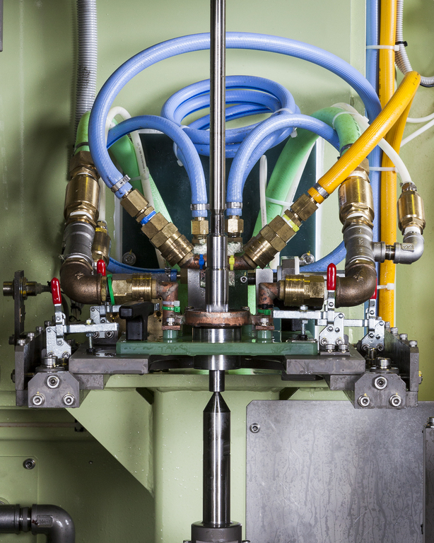
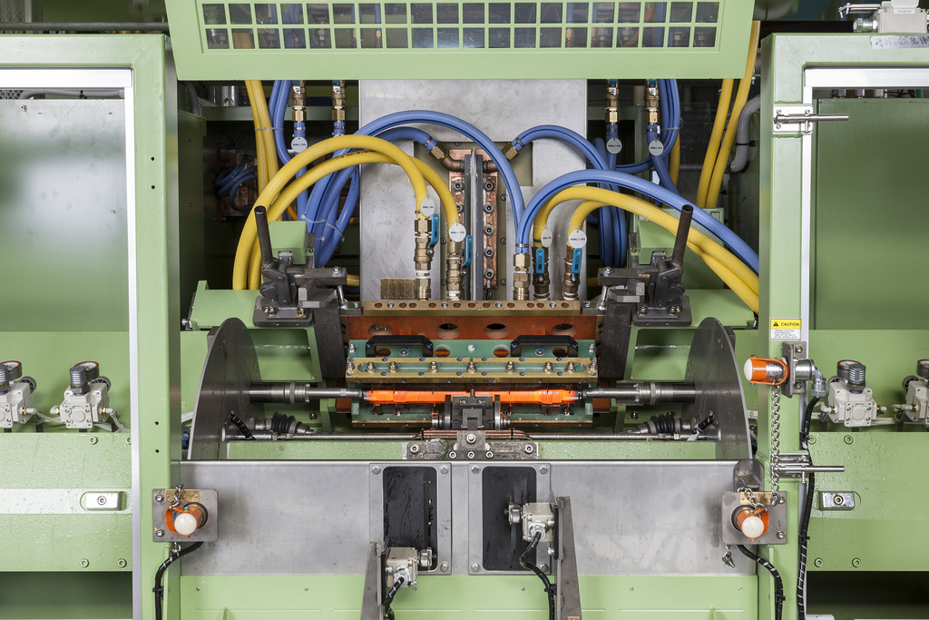
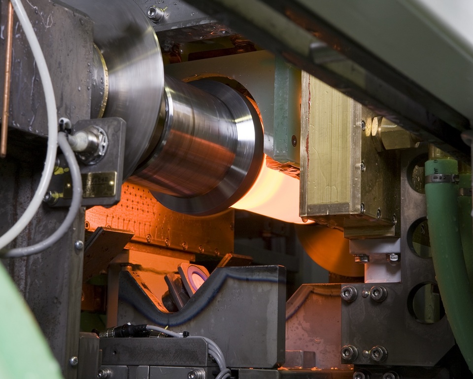
【Crankshaft Quenching Machine】
When quenching pins and journals of crankshaft simultaneously, miniaturizing transformers (disk transformer) or quenching towards the same direction as turning pins allows formation of a quenching layer along a pin diameter.
“Power reduction method,” top and bottom uniformed quenching technique by reducing the output on the pin top for R-quenching, can minimize the possibility of distortion.
The above quenching technique can be in-line and for such case, we will gladly design to match the customer’s request.
Please feel free to contact us.
-415
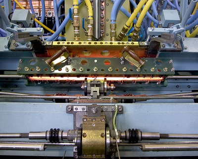
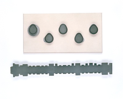
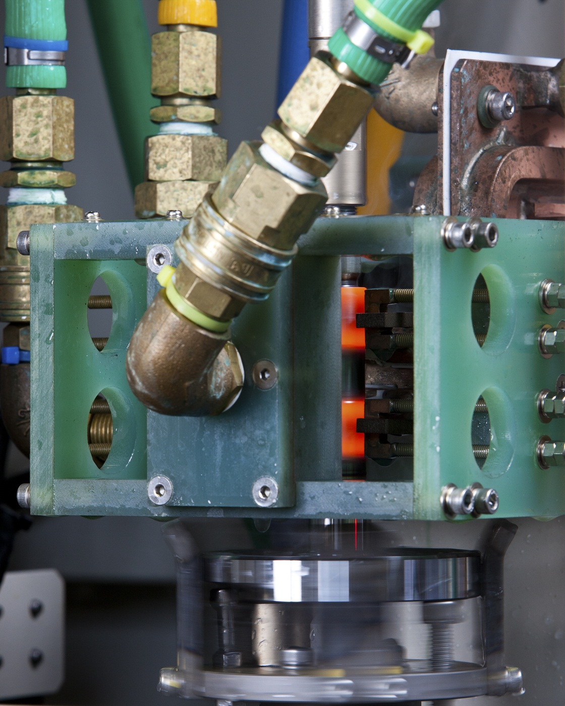
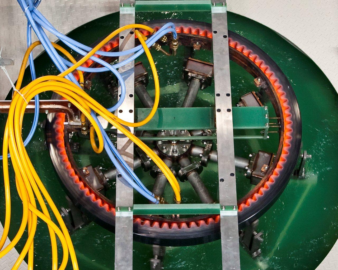
A high frequency quenching with a numerous track records in multi turn coil.
By applying a high frequency electrical current evenly to place where quenching is required in an inner groove, a deep uniformed quenching layer can be formed without any overheating, melting, or temperature differences.
A central coil quenching provides plentiful quenching depth for R while leaving no uneven quenching depth, uneven depth quenching, or burn deformation behind,
Since our coils are highly functional, highly durable, and highly precise, meaning, overall running cost can be reduced through less coil repair cost, less electricity usage amount, and less quality inspection process after coil exchange.
TY
-464
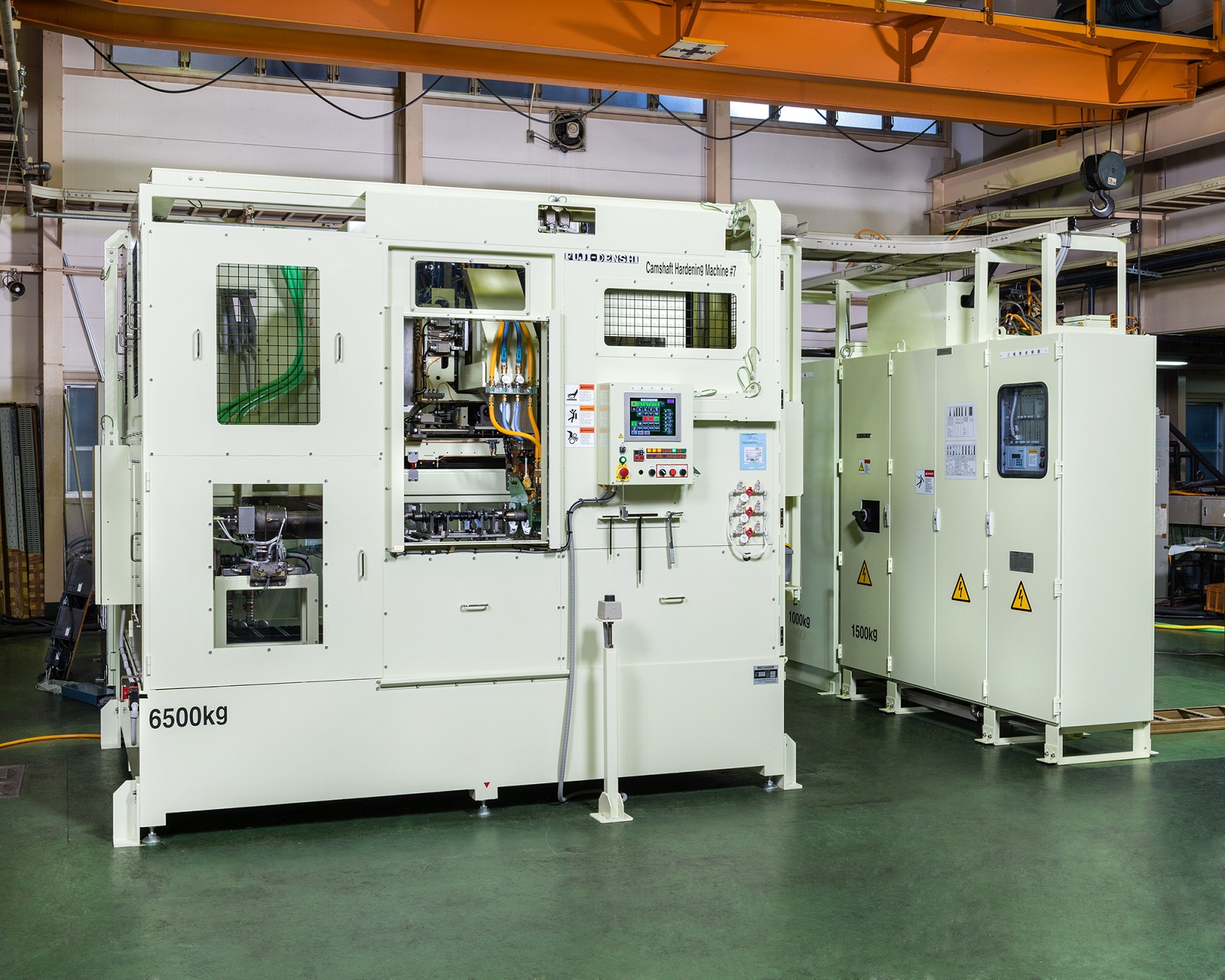
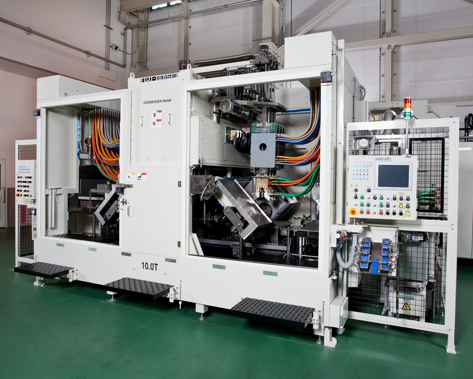
【Ordered Equipment】Drive Shaft Induction Quenching Equipment
[Future]
①A single unit production 225 per an hour.
②Compared to a movable induction quenching machine, a single shot system is 40 ~ 50% energy savings.
③40% better diameter ratio of induction quenching depth, resulting in improved fatigue strength.
④Less than 1/1000 of max length bending and low distortion treatment is applicable.
IT

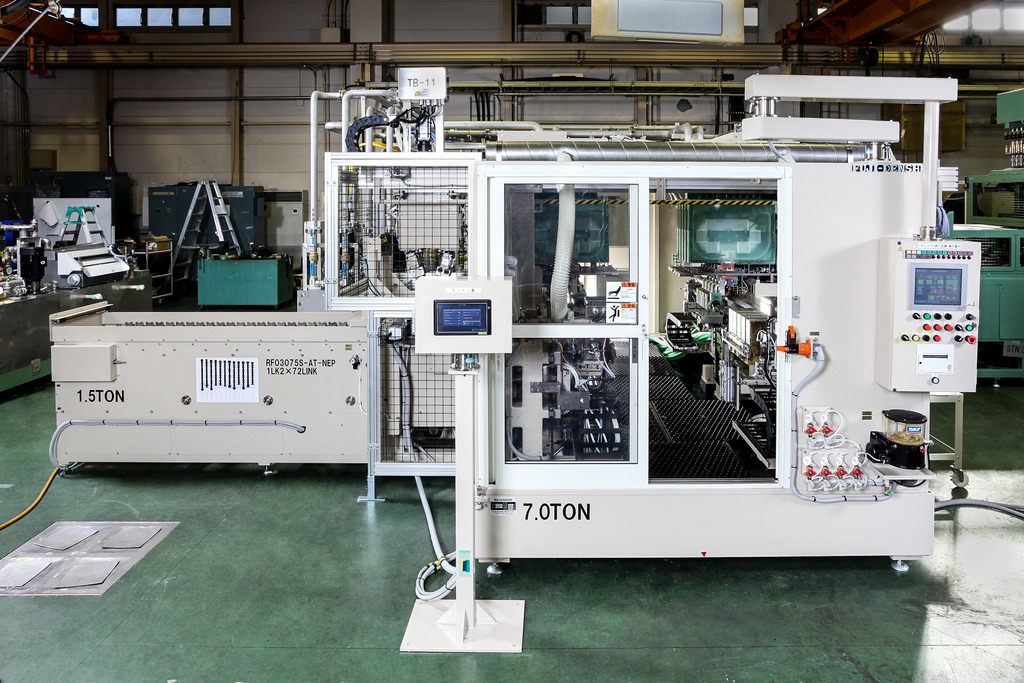
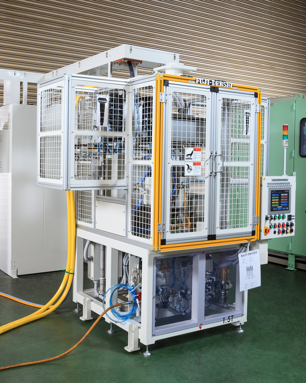
[Idler Hardening Machine]
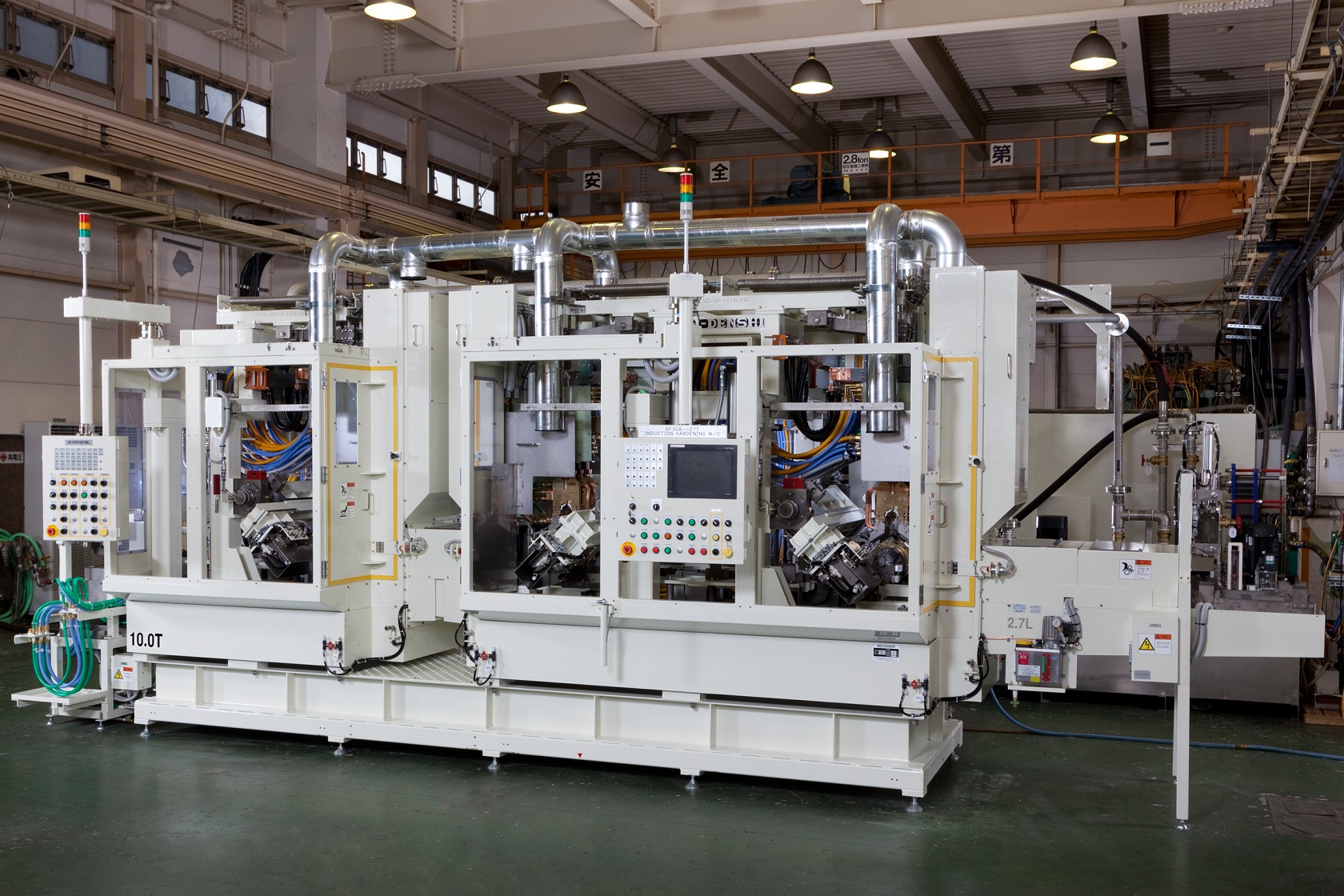
At Fuji Denshi, we manufacture and sell induction hardening machines
and also do job heat treatment.
This photo shows the hardening of an idler.
With our original technology, we achieve high strength and precision
hardening even for difficult large parts.
Our one-shot circumference hardening ensures high productivity for
large parts such as gears, idlers, and rollers.
Traditional hardening methods cannot prevent uneven hardening.
Also, when using ring coils, hardening must be done separately
on both sides of the idler.
With our methods, our original semi-open coil repeats heats with
intermittent breaks, gradually heating the rotating workpiece and
preventing unevenness.
This method also decreases total consumed power and greatly
reduces cycle time, achieving high productivity.
We manufacture induction heating machines and do job heat treatment.
This photo shows our originally developed induction heating converter FOCUS.
Manufactured entirely in-house from design to assembly,
we supply our customers with domestically made, guaranteed products.
Conversion efficiency is top class in the industry at 95%
and contributes to energy and cost savings.
~Induction Hardening Converter Development~

Fuji Denshi's crankshaft hardening utilizes the Elotherm method,
heating the rotating workpiece with a semi-open coil.
Design and manufacturing of high quality crankshaft hardening
machines requires advanced technology.
After implementing this advance method from early on,
it has been regarded worldwide and established a vast track record.
Fuji Denshi was selected as a Global Niche Top Company 100 in 2013.
Feel free to send all your inquiries about hardening and other heat treatments to us.
~Osaka Fuji Electronics Industry Crankshaft Hardening Machine~

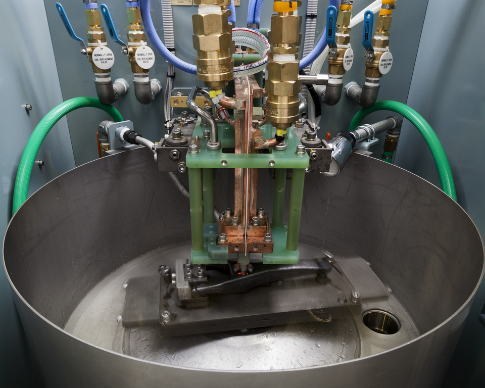
[Fuji Denshi Job Heat Treat Plant]
The large dip-quench hardening machine installed in our job heat treat plant
is mainly used for large gears and rollers.
It can treat parts up to 1.8m in diameter.
The photo shows the dip-spray process in action.

At Fuji Denshi, we design, manufacture, and sell induction heating machines
as well as do job heat treatment and prototype development.
The photo shows our stub shaft axle hardening and reheating machine.
The one-shot hardening method using our line coil achieves an ideal case
pattern even with the varying diameter of the workpiece, while saving energy.
The entire length of the workpiece is quenched simultaneously,
ensuring the residual heat over the part's length is even and
preventing cracking and uneven case hardness and depth.
(Even heating / Even quenching)
Heating and quenching are both even over the entire surface,
so runout is kept at a minimum even without the need for a straightening roller.
The residual stress along the axle axis contribues to large increases
in the part's durability and strength.
(2x by comparison)
Scan hardening can easily cause uneven hardness and low axial strength.
Our one-shot hardening requires only half the power of scan hardening to better results.

[Fuji Denshi Job Heat Treat Plant]
The small dip-quench hardening machine installed in our job heat treat plant
is mainly used for gears, rollers, and bearing races.
It can treat parts up to 0.65m in diameter.
Larger parts are treated with our large dip-quench hardening machine.
We recently introduced our originally developed compact transistorized converter, FIT.
FIT is suitable for low power applications such as hardening, heating, and brazing.
Continuing in the line of our FUJI-ELOMAT converter, the new FIT
is a less expensize option.
The high conversion efficiency results in at least a 55% decrease in power consumption
and 75% decrease in running cost compared to vacuum tube converters.
Our FIT converter is suited for various application including brazing.
We await your inquiry!
The photo shows a cut sample of an automobile engine camshaft hardening by our original machine.
At Fuji Denshi, we developed the eccentric hardening method for camshafts.
The coil follows the rotating cam in an eccentric pattern, achieving an
even casing and stable residual stress over the whole cam.
Cracking on the nose from overheating and post-grinding are prevented for high productivity.
The photo shows a cut sample of an automobile powertrain lebro joint
(cross groove universal joint) whose outer has been hardened by our machine.
We used our original SMT coil for lebro joint and BJ outer inner surface hardening.
By one-shot hardening the rotating workpiece, an ideal casing is achieved.
The stem section is hardened by single shot hardening using our specialized semi-open coil.
This method achieves an ideal hardened pattern along the outer diameter all the way to the corners while maintaining high productivity.
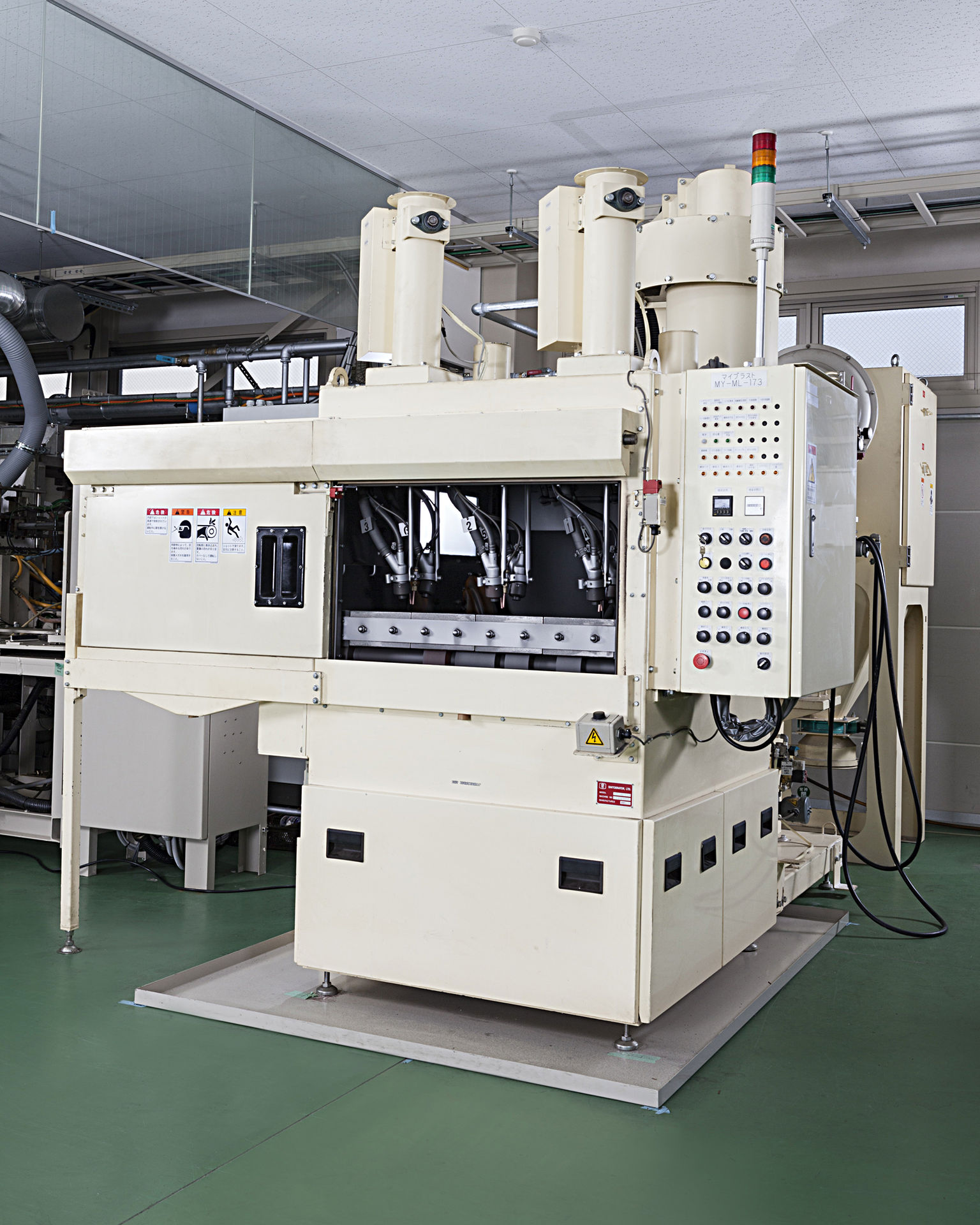
At Fuji Denshi, in addition to our specialized hardening and reheating processes,
we also perform post-processing.
Our shot blast machine is mainly used for shaft post-processing and can process
rod-shaped parts up to 780mm in length.
Leave your post-processing needs to us.
The photo shows the hardening station of an automobile power train CVJ
(constant velocity joint) outer surface induction hardening
and reheating machine.
The outer stem and cup grooves are hardened at one station
using the same converter.
Reheating is done at a separate station with a separate converter.
※At Fuji Denshi, we refer to tempering as reheating to differentiate
from furnace methods.
The process on this machine is
・loading
↓
・stem heating
↓
・stem quenching, cup heating
↓
・cup quenching
↓
・reheating
↓
・after quenching
↓
・unloading
By combining the hardening stations while keeping the reheating
station separate, we achieved a remarkably short cycle time of
under 30 seconds per workpiece while maintaining high quality.
The photo shows an automobile V6 engine crankshaft induction hardening
and reheating machine.
This machine is installed in-line at an engine plant.
It receives the workpiece from the previous process, performs hardening
automatically, and sends the workpiece to the next process.
The workpiece is loaded from the port on the right.
First the pins are induction hardened at the right and center stations,
followed by the journals at the left station.
Finally the work is unloaded from the port of the left.
This machine performs flat hardening, which in general is a simpler process,
but to achieve the specified short cycle time of under 50 seconds,
the machine was designed with two converters and three hardening stations for high productivity.
~Crankshaft Induction Hardening Machine Flat Hardening
High Productivity Automobile Prats IH Heat Treat~
The photo shows the double axle vertical scan hardening station of
an induction hardening machine for automobile transmission parts.
The workpiece, a clutch release fork (clutch lever), is hardened
at the two tips by semi-open coils.
After heating, the workpiece is carried down and quenched outside of the coil.
The green plate seen behind the coil is the quenching jacket,
which sprays quenching water from diagonally above the workpiece.
In addition to one-shot hardening as seen in the photo, the coils and jigs
can be exchanged for vertical scan hardening as well.
~Transmission Parts Induction Hardening Machine ③ Automobile Parts
IH Heat Treat~

We design and manufacture crankshaft hardening machines.
The photo shows an automobile V6 engine crankshaft induction hardening and reheating machine.
This machine is installed in-line at an engine plant.
It receives the workpiece from the previous process, performs hardening
automatically, and sends the workpiece to the next process.
The workpiece is loaded from the port on the right.
First the pins are induction hardened at the right and center stations,
followed by the journals at the left station.
Finally the work is unloaded from the port of the left.
This machine performs flat hardening, which in general is a simpler process,
but to achieve the specified short cycle time of under 50 seconds,
the machine was designed with two converters and three hardening stations
for high productivity.
The photo shows the hardening station of a motorcyle engine assembly
crankshaft induction hardening and reheating machine.
※At Fuji Denshi, we refer to tempering as reheating to differentiate from
furnace methods.
In the photo, two sections of the shaft are induction heated.
The spray quenching jacket is combined with the coil unit for a rapid
heating-quenching process.
To perform hardening and reheating with the same machine, the converter is
designed to switch between two frequencies.
Even with two heating-quenching cycles, the cycle time is kept under 1 minuteper workpiece.
~Assembly Crankshaft Induction Hardening Machine Reheating Machine
Double Axle Parts IH Heat Treat~
The photo shows the hardening and reheating stations in a automobile propeller
center bearing shaft induction hardening and reheating machine.
On the right with the green spray quenching jacket is the hardening station.
On the left in the brown box is the reheating station.
※At Fuji Denshi, we refer to tempering as reheating to differentiate from
furnace methods.
The hardening and reheating stations are divided and have separate converters
to achieve a cycle time of under 30 seconds.
This design achieves both compactness and high productivity.
The photo shows the hardening station of a vertical scan induction hardening machine
for shafts used in motors, generators, and alternators.
This automatic machine can induction hardening various motor shafts from
automobile alternators to vessel generators.
Our vertical scan hardening machine can be designed to move not only the workpiece, but also the coil and power transformer unit.
With this design, we decreased the size of the hardening station and
the entire machine as well as made loading and unloading easier.
As a result, this machine performs high quality hardening while
decreasing operation time.
[Job Heat Treat]
The photo shows a camshaft induction hardening and reheating machine.
This machine hardens two camshafts simultaneously with manual loading
and automatic unloading.
Fuji Denshi's camshaft hardening machine uses our patented eccentric
tracking mechanism.
The coil follows the rotating cam nose to achieve even heating.
Our original coil design smoothly heats the cam and prevents temperature
difference over the cam surface.
The quenching jacket is designed to control the water volume for even
quenching of each cam.
Using these technologies, cracking and uneven residual stress are reduced,
minimizing cracking during grinding while also achieving an even
casing and low runout.
The high-speed design also contributes to shorter cycle time.
Fuji Denshi's camshaft hardening machine uses our patented eccentric
tracking mechanism.
The coil follows the rotating cam nose to achieve even heating.
Using these technologies, cracking during grinding is prevented
while achieving an even casing and low runout.
The high-speed design also contributes to shorter cycle time.
[Custom-made Machines]
The photo shows the heating station of an automobile engine
camshaft pump cam induction heating machine.
To austemper the ductile iron pump cam, the cam is heated to over 1,100°C
and quenched in the adjacent salt bath.
To effectively heat the triangular shaped target area,
the rotating workpiece is heated with low frequency using a multi-turn coil
until a certain depth is reached.
After thorough calibration, we were able to meet the severe
heating specifications of minimum 1,100°C and range ±20°C
for two differently shaped target areas.
The photo shows the hardening station of a truck powertrain axle shaft induction hardening machine.
The multi-diamater axle shaft surface is evenly heated using our
semi-open line coil.
In the photo, the quenching jacket is raised, but during the actual process,
the jacket rotates 90° forward and moves down to the workpiece
for spray quenching.
The horizontally oriented workpiece is held by the centering unit,
then rotated by the straightening roller from below during heating
and quenching.
This method achieves hardening with low run out for thick, long,
and multi-diameter shafts.

The photo shows the hardening station of an automobile power train CVJ
(constant velocity joint) outer surface induction hardening and
reheating machine.
The hardened ares are the outer stem and cup grooves.
As seen in the photo, as the workpiece rotates the stem is induction heated.
The brown heating coil around the workpiece is our original semi-open line coil.
The benefits of our line coil include:
- deep hardening depth in the curved corners of multi-diameter shafts
- continuous case pattern over the shaft, curved, and flange sections
to prevent soft areas and achieve durability
- simple loading and unloading for short cycle time
With these features, this machine achieves a cycle time of
under 30 seconds per workpiece.
[Custom-made Machines]
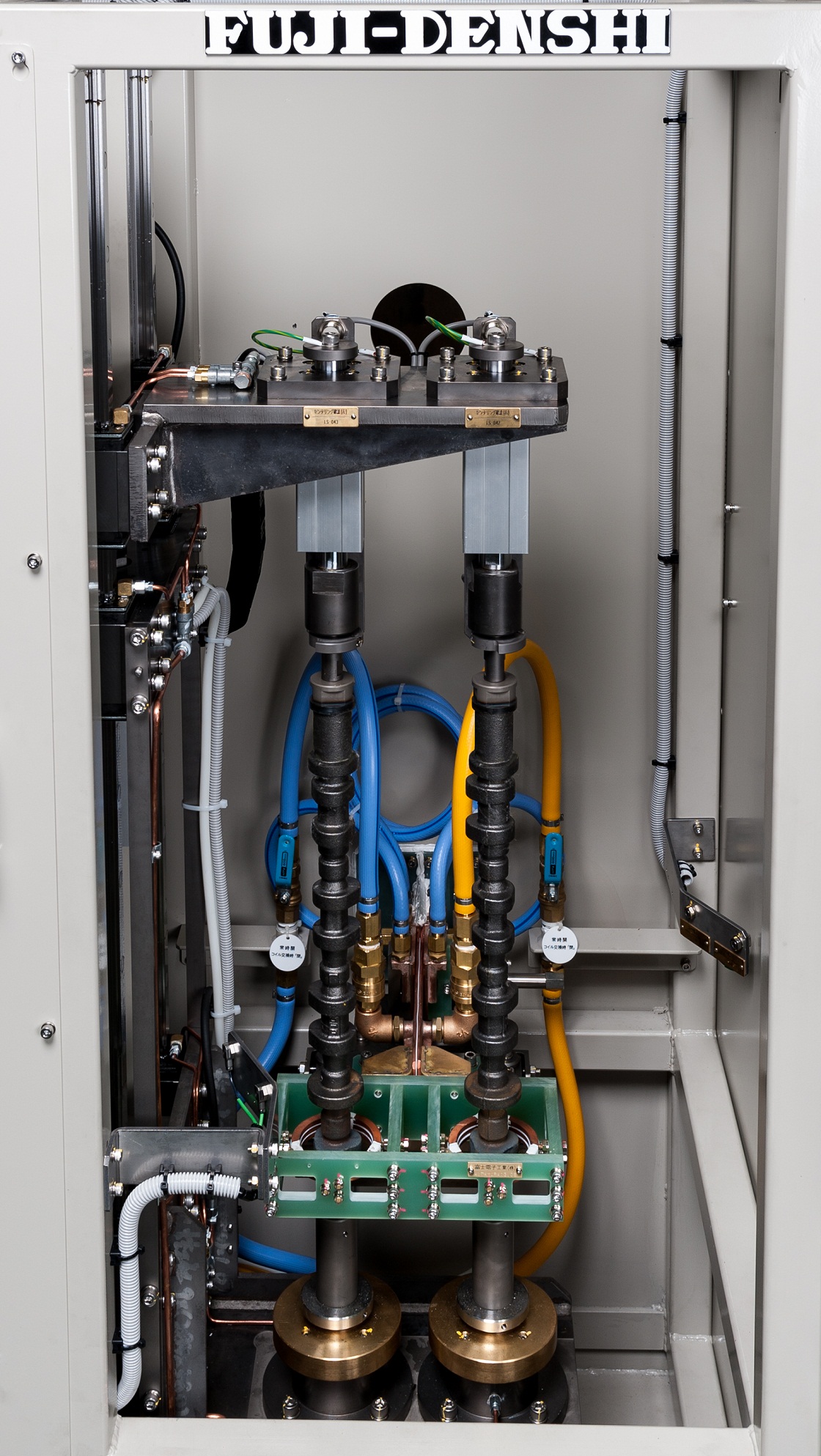
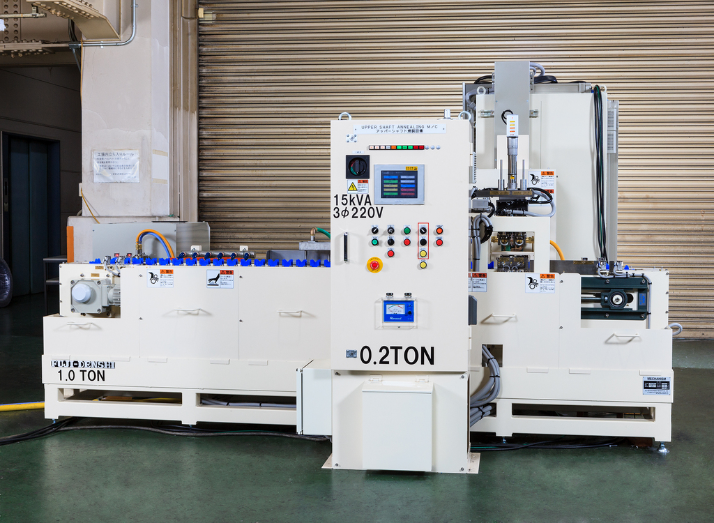
The photo shows an automobile steering upper shaft
induction annealing machine.
After forming with a press, the desired sections of the hardened workpiece
are induction heated for annealing.
One converter is used to anneal two workpieces simultaneously,
allowing for a compact machine design.
※The size of the manual loading/unloading machine without conveyor
is seen on the right.
We continue to develop methods to make our machines
as compact as possible.

The photo shows an automobile powertrain driveshaft (half shaft)
induction hardening machine.
In the front is the hardening machine and above it are two gantry loaders
for loading and unloading.
In the back left is the incoming panel and converter.
The workpiece in the center of the hardening machine is glowing red
during heating.
To the left of the hardening machine, a workpiece is waiting on a jig.
The same type of jig is also to the right of the machine, not seen in the photo.
The workpiece is picked up by the robotic arm, turned horizontally 90˚,
carried over the machine by the gantry loader and loaded
into the heating station.
After heating and quenching, the other gantry loader unloads the workpiece
and carries it to the next process.
This machine was specially designed for our semi-open line coil
and achieves a remarkably short cycle time of 20 seconds per workpiece.

We manufacture driveshaft induction hardening machines.
[Machine Features]
① High productivity of 225 parts/hour
② Single shot method for 40~50% energy savings versus scan hardening
③ Case depth of over 40% of diameter to achieve high fatigue strength
④ Originally developed straightening roller to prevent run out during hardening
Please contact us for your questions and concerns about driveshaft hardening.
~Driveshaft Induction Hardening High Productivity Energy Savings
Fatigue Strength Low Runout~

Double Axle Vertical Scan Induction Hardening Machine 2 Units
These machines were installed in a customer's overseas job heat treatment plant.
The inner surface of the 400mm length workpiece is induction hardened.
As the inner surface diameter ranges between 50~120mm,
the converter is designed to switch between two frequencies.
We made special adjustments to the machine's motor positioning
to meet our customer's request to minimize the height of the machine.
The height of the loading/unloading unit was also designed
to match the height of the operator.
This is our crankshaft induction hardening machine, able to treat crankshafts
for automobiles, agricultural machinery, construction machinery and more.
The machine can be adapted for a variety of crankshafts by
retooling the coil and jigs and other adjustments.
It is also able to perform hardening of split pins for V engine crankshafts.
With manual loading/unloading, after placing the workpiece on the front left jig,
the jig moves to the center and carries the workpiece to the back
of the machine.
In the back station, the pins and journals are hardened.
If the front station, the crankshaft oil hole section is hardened.
After hardening, the work are carried to the center and unloaded to the right.
While being extremely flexible, this machine also has high productivity.
This large dip quench induction hardening machine is installed
in our job heat treat plant.
Outer ring hardening: up to 1800mm diamater, 350mm thickness
Inner ring hardening: up to 1500mm diameter, 150mm thickness
This machine performs one-shot hardening for large gears,
bearing races and more up to the above dimensions.
For gear hardening, this machine features
- even heating by ring coil
- even quenching by dip spray
to minimize runout and cracking.
By heating in two stages, preheating and main heating,
the case depth is deep even in the gear grooves.
Please contact us with your job heat treatment needs.
[Custom-made Machines]
This is an induction annealing machine for automobile pinion shafts.
After the entire surface is hardened by carburizing, only the tip section
is annealed by induction.
Annealing does not require rapid quenching like hardening,
so the machine design is very compact.
As seen in the photo, the work is automatically loaded from the left
and carried to the annealing station.
After annealing, the workpiece is automatically unloaded.
We continue to develop machines with high productivity
using the simplest possible design.
The workpiece in the center of the hardening machine is glowing red
during heating.
The green box with handles is the coil unit, featuring a semi-open coil unit
positioned over the workpiece.
For muilt-diameter shafts, our machines are designed so the case depth is
sufficient even in the cruved corners of the shaft surface.
The workpiece shown is the thinnest and lightest of its kind in the industry,
and our machine is designed to make precision hardening possible
using our dip spray quench method and straightening roller for low runout.
~Driveshaft Induction Hardening Machine② Automobile Parts
IH Heat Treat~

This photo shows the heating station of our automobile transafer shaft
and helical shaft induction annealing machine.
After the entire surface is hardened by carburizing,
only a section is annealed by induction.
The photo shows the workpiece after annealing.
The flange shaped section of the middle workpiece appears blue
after being heated.
While we at Fuji Denshi maintain induction hardening as one of
our specialties, we also specialize in annealing of parts hardened
by carburizing, machining, and welding.
This photo shows out automobile engine crankshaft induction
hardening machine.
This machine is installed in-line at an engine plant.
It receives the workpiece from the previous process,
performs hardening automatically, and sends the workpiece
to the next process.
The workpiece is loaded from the port on the right.
First the pins are induction hardened at the right station,
followed by the journals at the left station.
Finally the work is unloaded from the port of the left.
This particular machine is specified for flat hardening of
4-cylinder crankshafts,and shows the common features
of our machines, compactness and short cycle time.
As a result, it has a cycle time of under 45 seconds per cycle
for extremely high productivity.
The photo shows the heating station of an automobile engine
camshaft pump cam induction heating machine.
To austemper the ductile iron pump cam, the cam is heated
to over 1,100℃ and quenched in the adjacent salt bath.
Pictured to the right are the transistorized converter and control panel,
and to the middle and left are the hardening machine and matching panel.
Loading/unloading is done by robot, and 2 workpieces are heated
at the same time. As a result, 2 workpieces are treated in under 1 minute.
For austempering, the heated workpiece is quickly unloaded
by the robot and transported to the salt bath.
This machine was designed for extreme compactness,
as the quenching water circuits in typical hardening were not necessary.
~Camshaft Pump Cam Induction Heating Austemper Machine ①
Automobile Parts IH Heat Treat~

This photo shows the hardening station of our autmobile engine
crankshaft flange hardening machine.
The workpiece is loaded/unloaded from above by robot.
After the workpiece is set on the rotating jig, the coil unit moves forward
to the heating position, and heats the workpiece as it rotates around its axis.
The photo shows the crankshaft flange being heated by the induction coil,
which is behind the green disc-shaped spray jacket.
After heating, the coil unit moves slightly back to the quenching position,
and quenching water is sprayed onto the workpiece from the spray jackets.
[Custom-made Machines]
This is the flange oil seal hardening station of our all-purpose crankshaft
hardening machine, which treats crankshafts for automobiles,
agricultural machinery, construction machinery, and more.
The machine can be adjusted for various types of crankshafts
by exchanging and repositioning the coils and jigs.
In the photo, the flange section of the crankshaft is induction heated
by a ring coil.
The coil is housed in green resin insulation to prevent induction
of the surrounding machine,while the coil is cooled by a continuous flow
of cooling water through its copper piping.

The photo shows the hardening station of our all-purpose hardening
machine for automobile parts.
This machine has two hardening stations, enabling it to harden
two different types of workpieces if equipped with different coils and jigs.
Treatable parts include:
・Shift fork
・Clutch release fork
・Lever striking
・Bracket
and other such parts for automobile transmission, which have difficult shapes
including curves and teeth.
In the photo, the teethed section of a bracket is being induction hardening
at the right-hand station.
To the left of the heated workpiece is the gold-colored spray quench jacket,
which rapidly quenches the workpiece after heating.
At the left-hand station, a lever striking is sitting on the jig ready for heating.

[Job Heat Treatment]
The photo shows the shaft hardening machine in our job heat treatment plant.
The left- and right-hand station are independent, allowing for treatment of
different workpieces.
Shafts from diameter 14~17mm and length 145~180mm can be treated.
Please contact us for your job heat treatment needs.
The photo shows our truck powertrain axle shaft induction hardening
and reheating machine.
※At Fuji Denshi, we refer to tempering as reheating to differentiate
from furnace methods.
In the photo, the rotating shaft is induction hardened using our
semi-open line coil.
The green device above the workpiece is the heating coil and the gold devices
in front of and behing the workpiece are the quenching jackets.
To quickly quench the entire shaft, two large volume spray jackets are placed
on both sides of the workpiece.
Even considering the large size of the workpiece, this machine achieves
a cycle time of under 2 minutes for hardening and reheating one workpiece.
The photo shows our automobile engine camshaft induction hardening
and reheating machine.
To increase productivity, the machine was designed with two stations,
which alternate between hardening and reheating using one converter.
※At Fuji Denshi, we refer to tempering as reheating to differentiate
from furnace methods.
Loading/unloading is done manually. After placing the workpiece
on the front right side jig, a robotic arm carries it to each station.
After hardening, the arm carries the workpiece to the front left port.
This machine also features our patented coaxial coil lead which has
lower lead power loss. The coil lead is shielded from the induced current,
resulting in longer coil life.

The photo shows the hardening station of our automobile camshaft
induction hardening and reheating machine.
In the photo, two noses of two camshafts are being induction heated.
After heating, the coils move laterally and at the same time
the quenching jackets moves from the left over the cams
to rapidly quench them.
Our camshaft hardening machine uses our patented eccentric tracking
mechanism, where the hardening coils follow each cam nose as the shaft
rotates to achieve even heating.
Our originally developed coils are also designed to prevent temperature
difference over the cam surface.
The quenching jackets are designed to even quench each cam without
using excess quenching water.
Using these technologies, we are able to reduce cracking during hardening
as well as cracking during grinding caused by uneven stress, while achieving
an even cashing and low runout.
~Camshaft Induction Hardening Reheat Automobile Parts IH Machine②~
The photo shows the heating station of an automobile engine camshaft
pump cam induction heating machine.
To austemper the ductile iron pump cam, the cam is heated to over 1,100℃
and quenched in the adjacent salt bath.
To effectively heat the triangular shaped target area,
the rotating workpiece is heated with low frequency using
a multi-turn coil until a certain depth is reached.
In the photo, the pump cam is heated to a depth close to the shaft axle.
After thorough calibration, we were able to meet the severe heating
specifications of minimum 1,100℃ and range ±20℃ for two differently
shaped target areas.
The photo shows the single rotating axis hardening station of
an induction hardening machine for automobile transmission parts.
The workpiece, a clutch release fork (clutch lever), is rotated
while heating the inner surface of the center hole.
Our original small spiral multi-turn coil to treat the extremely difficult
multi-diameter hole inner surface.
After heating, the workpiece is carried down out of the coil
and spray quenched by jackets on both sides.
The photo shows our vertical scan induction hardening machine for shafts
used in motors, generators, and alternators.
This machine can treat various shafts including for automboile alternators
and ship generators.
By setting parameters including output power, frequency, coil type,
workpiece size, feed speed, and quenching water flow,
our vertical scan hardening machine achieves high repeatability
As a result, runout is kept to a minimum for high quality hardening
and reduced operation time.

[Custom-made Machines]
The photo shows the hardening station of our double axis
vertical scan induction hardening machine.
This machine can treat workpieces from inner diamater Φ50 to Φ120.
In the photo, one coil unit is simultaneously treating two workpieces.
Quenching water is sprayed from the hole in the receive jig seen
at the bottom for rapid quenching.
In this scan hardening machine, the heating coil and quenching jacket
are combined into one unit.

The photo shows the heating station of our automobile engine
camshaft induction hardening and reheating machine.
3 coils are used to simultaneously heat 6 cam noses of a V6 engine camshaft.
Our original coil design prevents cracking from overheating of the cast iron camshaft.
The quenching water volume is also controlled to further prevent cracking.
~Camshaft Induction Hardening Reheat Machine②~
The photo shows the hardening station of our all-purpose hardening machine
for automobile parts.
This machine has two hardening stations, enabling it to harden
two different types of workpieces when equipped with different coils and jigs.
Treatable parts include:
・Shift fork
・Clutch release fork
・Lever striking
・Bracket
and other such parts for automobile transmission, which have difficult shapes
including curves and teeth.
To treat curved sections, a MOSFET transistorized converter
capable of outputing frequencies of 100~300kHz is used.

[Custom-made Machines]
At Fuji Denshi, we design and manufacture induction heating machines
to our customer's specifications.
The photo shows a truck powertrain axle shaft induction hardening machine.
The workpiece can be seen at the hardening station in the center of the photo.
This machine is able to treat shafts of various diameters and length.
This machine was designed for manual loading/unloading
due to the small lot size of truck axle shafts and the need to treat workpieces
of different specifications.
The green unit under the workpiece is the heating coil.
To minimize runout, this machine is equipped with a semi-open line coil
and a straightening roller.
The box-shaped unit in the back of the hardening station equipped with hoses
is the quenching jacket.
During hardening, the quenching jacket rotates forward 90˚ and the center door
closes to prevent quenching water from splashing.
~Axle Shaft Induction Hardening Machine① Automobile Parts
Induction Heat Treat~
As the demands for lighter, stronger, more efficient, and more eco-friendly
engine manufacturing increase, we at Fuji Denshi have supplied over
250 crankshaft hardening machines domestically and overseas.
Our crankshaft hardening technology, based on our semi-open coil
and rotating tracking method, includes numerous innovations which combine
to minimize runout.
Our fillet hardening technology has become a must-have for stonger
and lighter crankshafts.
We strongly encourage manufacturers currently using carburization
to consider our induction technology to improve cost, lead time, and runout.

[Heat Treat Plant]
This machine can treat 3 different automobile transmission parts.
This system has 3 hardening machines sharing 1 converter.
From the left,
・single rotating axle hardening machine x 2
・double axle vertical scan hardening machine x 1
By changing the coils and jigs, all three machines can be retooled
to treat various workpieces.
The converter is also specified to switch between four frequencies
(80kHz, 100kHz, 200kHz, 300kHz) to treat various parts.
It also features an interlock circuit control to allow treatment of
various parts in succession.

[Custom-made Machines]
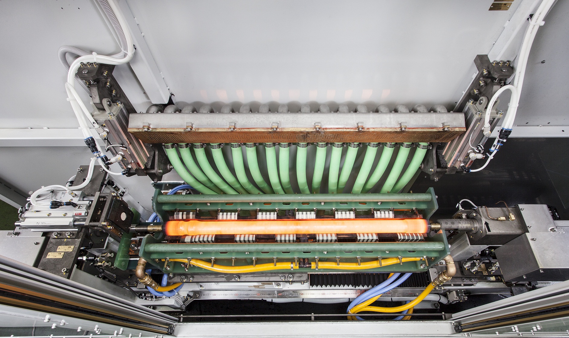
The photo shows an automobile steering upper shaft induction annealing machine.
After forming with a press, the desired sections of the hardened workpiece
are induction heated for annealing.
The workpiece is carried by the belt conveyer and positioned by the centering unit.
Then it is lifted into the machine, inserted into the coil, and heated.
The coil is specially designed to heat two workpieces simultaneously.

This photo shows the heating station of our automobile transafer shaft
and helical shaft induction annealing machine.
After the entire surface is hardened by carburizing, only a section
is annealed by induction.
The workpiece is automatically loaded into the annealing station,
and after annealing is automatically unloaded.
By synchronizing loading and unloading, a shorter cycle time was achieved.
This machine is one example of our simple yet highly productive
induction heating machines.
[Job Heat Treat]
The photo shows hardening of the teeth of a gear.
After heating, the workpiece is lowered into the quenching water,
where it is sprayed by additional quenching water to achieve an even casing.
We have a large-scale and small-scale dip-spray hardening machine
in our heat treat plant, which together can treat parts up to diameter 1.8m.
We have also manufactured and installed this same machine in our customer's plant.

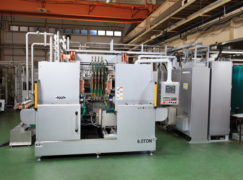
The photo shows an automobile engine crankshaft
induction hardening machine.
In the front right is the hardening machine,
to the left is the cooling water tank and quenching water tank,
in the center is the incoming panel,
and to the right is the transistorized converter.
The hardening machine has been designed to optimize compactness
and the overall layout was designed to meet our customer's specifications.
This machine is installed in an engine production line,
where it receives the workpiece from the previous process,
and automatically sends it to the next process after hardening.

The photo shows an automobile engine crankshaft induction
hardening machine.
This machine is designed for fillet hardening of pins and journals of
compact, lightweight crankshafts.
This machine is installed in an engine production line,
where it receives the workpiece from the previous process,
and automatically sends it to the next process after hardening.
The workpiece is loaded from the left, then the pins are hardened
at the left hand station.
The journals are then hardened at the righthand station,
before the workpiece is unloaded to the right.
This machine is specified for compactness and short cycle time
(under 60 sec/pc).
This was achieved by designing and manufacturing coils to control
the high power at the fillet corners using the Elotherm method.
☆ In the Elotherm method, semi-open coils track the rotating workpieces,
achieving low distortion and even casing.
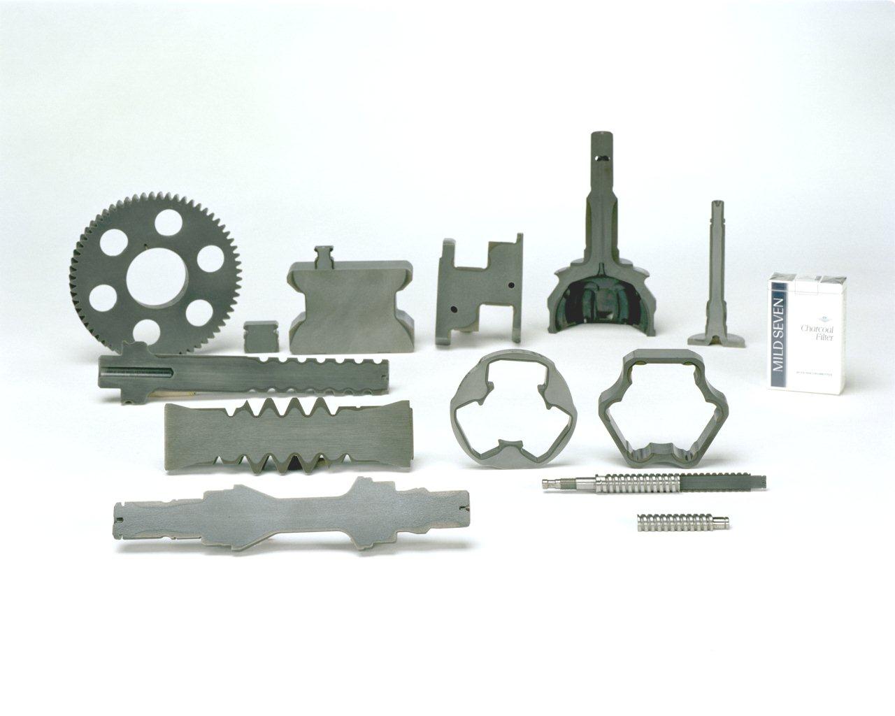
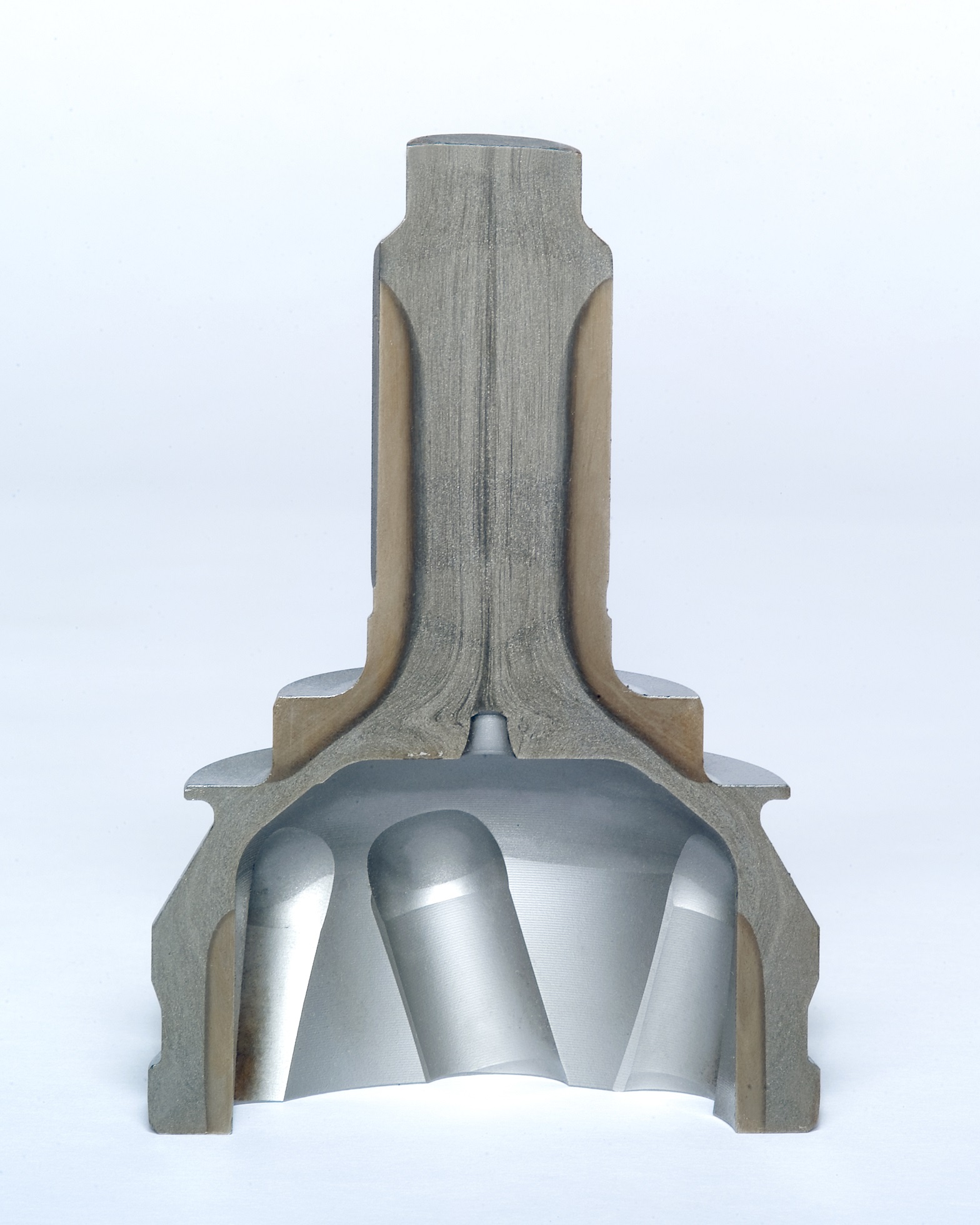
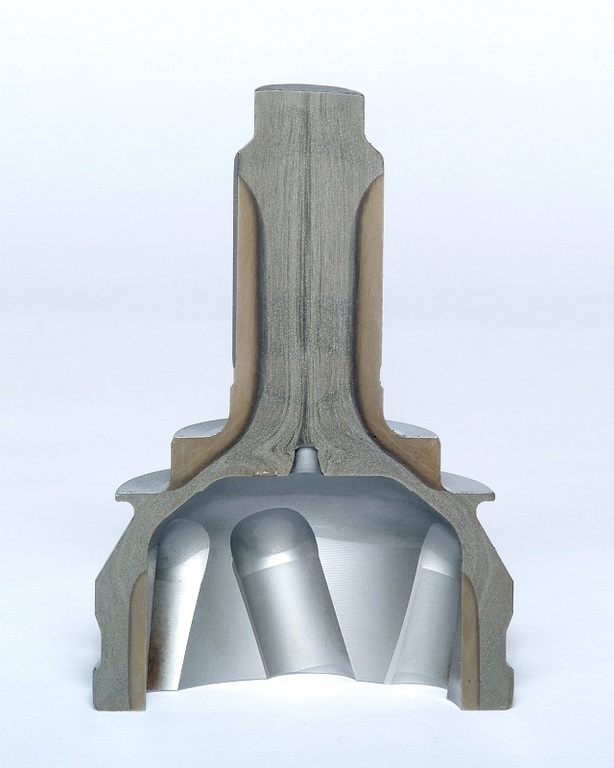
The photo shows cut samples of various machinery parts hardened
by our induction hardening machine.
The gray area of the cross section is the hardened casing.
As seen in comparison with the pictured cigarette box, the parts
are surprisingly small and the hardened areas are complexly shaped.
At Fuji Denshi, we apply our induction heating technology to meet
our customer's heat treat needs by supplying machines or providing
in-house job heat treat.
One of our specialties is heat treatment of large workpieces such as
construction machinery slewing bearing and machine tool beds and columns.
~Induction Hardening Cut Sample IH Heat Treat Automobile Parts
Production Machinery Parts~


