Language: 日本語 | English
Language: 日本語 | English

Forging is a process that makes three-dimentional objects out of materials by crushing, exciting and other deforming procedures.
Various shapes are possible. Consult with us.

Unlike conventional pipe benders that require fixed-radius dies, our CNC Freeform Pipe Bender allows full control over bend radius and angle through programmed processing. This innovative bending system eliminates the need for frequent die changes and enables highly complex bending operations.
Capabilities Beyond Conventional Pipe Bending
With our system, the following bending operations—previously impossible with traditional pipe benders—are now achievable:
Large-radius bends on the scale of several meters (large R bends)
Continuous variable-radius bends (compound R / progressive R) without intermediate straight sections
3D freeform curves by adjusting the axis angle of compound/progressive bends
Bend angles exceeding 180°
Multiple bend radii in a single continuous process—eliminating the need to change bending dies
Seamless 3D Data Integration
If you provide the 3D centerline data of your pipe (designed with straight and arc segments), we can instantly convert it into our proprietary CNC format using our data converter. This allows for rapid prototyping, much like a 3D printer for pipe bending.
Example Processing Program:
D=42.7
L=120 FF=25.00 FE=25.00
R=100.00 T=90.00 P=0.00 FE=25.00 FF=25.00
R=225.00 T=180.00 P=90.00 FE=25.00 FF=25.00
R=100.00 T=90.00 P=0.00 FE=25.00 FF=25.00
L=120 FF=25.00 FE=25.00
Parameter Definitions:
D = Pipe outer diameter (mm)
L = Length of straight section (mm)
R = Bend radius (mm)
T = Bend angle (°)
P = Axis angle at the connection between different R bends (°)
FF / FE = Relative speed of movement along the XY axis (relative to pipe feed speed)
Production & Custom Processing Available
We offer both small-lot prototype processing and full-scale production using our in-house CNC freeform pipe bending systems.
For inquiries, please prepare your drawings or specific bending challenges, and feel free to contact us!

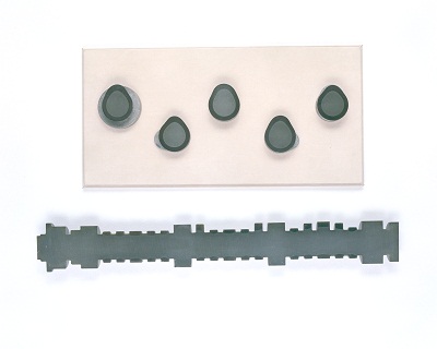
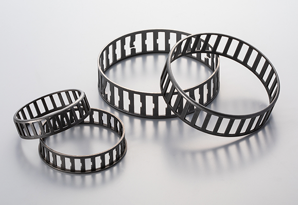
Nippon Forming specializes in manufacturing stainless steel plate springs for control cable fastening, designed for use in harsh environments.
[Features]
• Use of highly durable stainless steel materials
• Customization according to customer needs
• Adaptability to various cable sizes
[Product Overview]
• Applications: Control cable fastening in factories, outdoors, and warehouses
• Material: Corrosion-resistant stainless steel
• Size: Adjustable to cable size and quantity
[Main Use Cases]
• Outdoor control cable fastening
• Factory wiring management
• Warehouse equipment cable retention
• Power facility cable management
• Wiring fastening for heavy machinery and industrial equipment
[Processing Technology]
• Materials: SUS301, SUS304, SUS316, SUS631
• Die design considering springback
• Size range: Developed length 30mm-130mm, plate width 1mm-50mm
[Nippon Forming's Strengths]
• Optimal design through detailed consultation
• Highly durable products designed for long-term use
• Products suitable for use under harsh conditions
Nippon Forming is a specialized manufacturer of precision-processed wire and strip materials.
We work with various materials ranging from 0.1 to 5mm in diameter. Complex shapes are achievable through NC control.
[Company Information]
Nippon Forming Co., Ltd.
Headquarter & Main Factory: 1-23-2 Kanamachi, Katsushika-ku, Tokyo
Tsukuba Factory: 2924 Ujikai, Ishioka-shi, Ibaraki
https://www.forming.jp/eng/

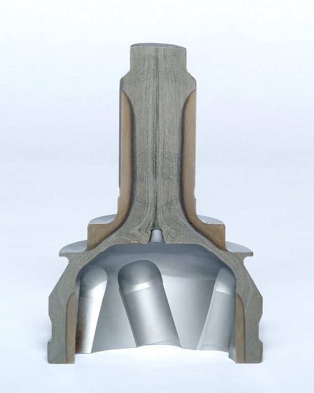
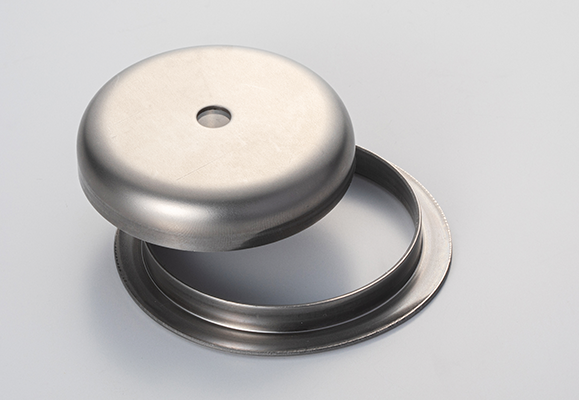
[Secondary Sheave Piston] Prototype Created by Converting from Casting to Sheet Metal Pressing
► Achieving the Shift from Casting to Sheet Metal Pressing through Process Innovation
※ This article introduces a case study of solving challenges in automotive parts prototyping by converting the manufacturing process of the secondary sheave piston from casting to sheet metal pressing.
[Challenges Faced in the Manufacturing Field]
In the development of automotive parts, there is a growing demand for lighter and higher-performance components. The secondary sheave piston, a crucial part of the CVT (Continuously Variable Transmission), faces weight and cost challenges when using conventional casting methods.
Furthermore, the following challenges emerge during the prototyping phase:
High costs in small-lot, multi-variety production
Difficulty in shortening lead times for both raw material production and machining
Ensuring quality assurance when transitioning manufacturing processes
Environmental and safety concerns in the production facility
Innovative Solution Through Sheet Metal Pressing Prototyping
✔ Advantages of Transitioning from Casting to Sheet Metal Pressing
Significant reduction in processing time through pressing
Control of material thickness during plastic deformation, allowing for extra thickness where needed
Enhanced workplace safety through cold processing
Greater design flexibility, enabling easy shape modifications
✔ High-Precision Processing with Advanced Equipment
Process optimization through press forming analysis
High-quality molds processed with precision machining centers
Stable forming with high-power hydraulic presses
Precision cutting using state-of-the-art 3D laser processing machines
High-precision inspection system using coordinate measuring machines (CMMs)
Key Factors for a Successful Process Conversion
► Comprehensive Support from Material and Process Selection to Quality Assurance
Material and process: Accelerated process optimization through press forming simulation
Cost reduction by minimizing physical trials with digital technology
Workplace improvements through cold processing
Quality: Rigorous quality management system based on ISO9001
► Technical Strengths
Fully integrated system from design to manufacturing
Low-cost and rapid process optimization using digital technology
Extensive processing equipment
Master-level expertise from skilled engineers
Customer Feedback
We saw significant improvements in QCD (Quality, Cost, Delivery) through process substitution.
— Head of Development, Major Parts Manufacturer A
The stability of quality was high, and we obtained valuable data for mass production considerations.
— Head of Technical Division, Automotive Parts Manufacturer B
Conclusion
Process conversion through sheet metal press prototyping is an innovative solution that simultaneously shortens development time and reduces costs. In particular, the benefits are evident in the case of the secondary sheave piston.
▶ Download Detailed Technical Materials
More detailed technical documents are available for download at the following URL:
https://ja.nc-net.or.jp/company/22325/dl/catalog/207206
Company Information
Company Name: Timec Co., Ltd.
Address: 197-1 Nishigori, Sōja City, Okayama Prefecture, 719-1164, Japan
TEL: +81-866-93-1269
FAX: +81-866-93-2540
Corporate Website: https://timec.co.jp/
Technical Consultation & Quotation Requests: https://ja.nc-net.or.jp/company/22325/inquiry/

► Challenges faced by the Automotive Industry
In the automotive industry, suspension members are critical structural components that influence both vehicle safety and ride comfort. In recent years, there has been a growing demand for both weight reduction and high rigidity, making it particularly challenging to ensure welding quality.
Suspension components require both high welding strength and dimensional accuracy. In particular, suspension members directly absorb impacts from suspension parts, making welding reliability crucial for overall vehicle safety.
► Technical Challenges
Key challenges in manufacturing suspension members:
・Controlling thermal distortion caused by welding
・Ensuring uniform welding quality in complex shapes
・Establishing optimal welding conditions to reduce spatter adhesion
・Overcoming welding difficulties due to gaps between materials and differences in plate thickness
[Problem Solving with Welding Technology]
Through years of prototype development, we have established the following solutions with our unique welding technology:
✔ Development of a Thermal Deformation Control System
・ Suppressing distortion through optimized welding sequences and positions
・ Ensuring dimensional accuracy with custom-developed welding jigs
・ Managing heat input through machine-monitored current control
✔ Quality Assurance System
・ Full inspection using 3D measurement
・ Strength verification through destructive testing
・ Weld defect detection via macro inspections
►Proven Reliability
○ Customer Feedback
The stability of welding quality is outstanding.
I was amazed by the high dimensional accuracy.
The quick turnaround time is impressive.
►Implementation Benefits
Feedback from companies that have implemented our solutions:
・ Defect rate: Reduced by 75% compared to conventional methods
・ Manufacturing lead time: Shortened by 20%
・ Overall costs: Reduced by 15%
*For more detailed case studies and performance data, please download our technical materials from the link below:
Technical Materials Download: https://ja.nc-net.or.jp/company/22325/dl/catalog/207206
For any inquiries, please feel free to contact us via our technical consultation and quotation request form.
Technical Consultation & Quotation Request: https://ja.nc-net.or.jp/company/22325/inquiry/
[Company Profile]
Company Name: Timec Co., Ltd.
Address: 197-1 Nishigori, Soja City, Okayama, 719-1164, Japan
TEL: +81-866-93-1269
FAX: +81-866-93-2540
Corporate Website: https://timec.co.jp/
Related URL: https://timec.co.jp/mind/

[Case Study]
Sheet Metal Fabrication of Intake Manifold (Aluminum Die-Cast)
– Achieving Shorter Prototype Lead Time and Cost Reduction in Mass Production –
► Recognizing the Challenges
In the 1990s, aluminum die-casting was the dominant manufacturing method for intake manifolds in the automotive industry. However, rising raw material costs and increased manufacturing expenses due to multi-cylinder engine designs led many parts manufacturers to seek alternative production methods.
Key challenges during the prototyping phase included:
・High cost of mold production
・Lengthy prototype lead times
・Limited flexibility in design modifications
・High costs for small-batch production
►Technical Approach
Our proposed sheet metal fabrication method offers a revolutionary approach that significantly reduces manufacturing costs compared to traditional aluminum die-casting.
Key technical points include:
・Material Selection: SPHC (hot-rolled steel plate) and STKM (carbon steel mechanical tubing)
・Optimized Design: Strength analysis and weight reduction using 3D CAD
・Manufacturing Process: Combination of press forming, laser processing, and welding technology
・Quality Assurance: High-precision dimensional verification using 3D measuring instruments
►Detailed Solutions
The sheet metal fabrication of the intake manifold was developed through the following phases:
1. Design Phase
・3D modeling using CAD
・Design of press molds and jigs for laser processing and welded assembly
・Development of DNC machining programs based on 3D models
2. Prototype Phase
・Mold and jig processing using DNC machining
・High-precision machining with a 5-axis laser cutter
・Precision welding by skilled technicians
3. Validation Phase
・Dimensional verification using 3D measuring instruments
・Performance evaluation through actual vehicle installation tests, followed by design optimization
・Durability testing and feedback-driven design improvements
►Implementation Benefits
This development project achieved the following results:
✔ Manufacturing Cost: Reduced by 40% compared to conventional methods
✔ Development Period: Prototype lead time shortened by 50%
✔ Weight Reduction: 20% lighter than conventional
✔ Design Flexibility: Significantly improved
These achievements were made possible by over 50 years of prototype development experience and a team of 160 skilled engineers. We continue to apply this technology to the sheet metal fabrication of various automotive components.
►Future Prospects
In recent years, some intake manifolds have transitioned to resin materials. However, the optimal manufacturing method depends on the required component characteristics and operating environment.
We propose the best manufacturing solutions, including sheet metal fabrication and hybrid approaches, tailored to each customer’s needs.
►Conclusion
Sheet metal fabrication of intake manifolds is a highly effective solution that achieves both cost reduction and weight savings.
For more details, please download our technical documents from the link below and discuss potential applications with your development team.
[Company Profile]
Company Name: Timec Co., Ltd.
Address: 197-1 Nishigori, Soja City, Okayama, 719-1164, Japan
TEL: +81-866-93-1269
FAX: +81-866-93-2540
Corporate Website: https://timec.co.jp/
🔹 Download Technical Documents:
https://ja.nc-net.or.jp/company/22325/dl/catalog/207206
🔹 Technical Consultation & Quotation Requests:
https://ja.nc-net.or.jp/company/22325/inquiry/
🔹 Related URL: https://timec.co.jp/

Oil Pan Prototyping and Development – A Critical Component for Engine & Transmission Performance
In the automotive industry, the oil pan plays a crucial role in ensuring the performance and reliability of engines and transmissions. This guide, based on over 50 years of experience in prototype development, addresses the challenges and solutions in oil pan manufacturing.
Key Challenges in Oil Pan Development
Currently, the automotive industry faces several challenges in oil pan production:
1. Strict control over material thickness reduction
2. High-precision surface quality for mounting areas
3. Reduction of lead time from prototyping to mass production
4. Maintaining cost competitiveness
Particularly in deep drawing press forming of oil pans using mild steel sheets, precise control over material thickness reduction is essential.
Customer Feedback:
Since these parts are used around the engine and transmission, oil leakage is absolutely unacceptable.
Technical Solutions
To address these challenges, we implement the following technological approaches:
1. Deep Drawing and Press Forming Simulation
Pre-evaluation using JSTAMP software
Prediction and optimization of material thickness reduction rates
Prevention of forming defects in advance
High-Precision Die Design & Manufacturing
2. High-Precision Die Design and Manufacturing
Precision design using 3D CAD
Uniform surface pressure distribution with unique die structure
Finishing by skilled technicians
3. Quality Assurance System
100% inspection with 3D measuring machines
Verification of mounting surfaces with dedicated inspection jigs
Operation of traceability system
Actual case studies have shown the following improvements:
✔ Prototyping period: Reduced by 30% compared to conventional methods
✔ Cost: Lowered by 30% compared to traditional techniques
✔ Mass production transition: Smooth and efficient ramp-up
Our expertise in deep drawing press forming, particularly in controlling material thickness reduction, is what sets us apart in manufacturing oil pans for engine and transmission components.
Founder’s Comment:
Only real technology can meet such strict requirements.
Proposal to Customers
We have even more detailed technical documents available. You can download them for free from the following URL:
https://ja.nc-net.or.jp/company/22325/dl/catalog/207206
Please feel free to contact us from the following form for technical consultations and quotation requests:
https://ja.nc-net.or.jp/company/22325/inquiry/
[Company Profile]
Company Name: Timec Co., Ltd.
Location: 197-1 Nishigori, Soja City, Okayama Prefecture 719-1164
TEL: 0866-93-1269
FAX: 0866-93-2540
Corporate Website:
https://timec.co.jp/
Related URL: https://timec.co.jp/

Industry Challenges
In manufacturing prototyping, achieving both high quality and short lead times is a significant challenge. In particular, lower arm assemblies—key automotive suspension components—require exceptional strength and precise machining accuracy. However, shortening the development period for such parts has been a persistent challenge.
Technical Solutions
By combining press forming analysis, high-output hydraulic presses, and 3D laser machining technology, we effectively address these challenges. The production of lower arm assemblies demands deep drawing techniques for enhanced strength and precision shaping using 3D laser processing.
The Importance of Lower Arm Assemblies
As a critical component in a vehicle's suspension system, the lower arm assembly connects the chassis to the wheels, directly influencing driving stability and ride comfort. This makes high strength and precise dimensional accuracy essential.
Quality Assurance through Integrated Production
✔ Design Phase: Utilizing advanced 3D-CAD systems like CATIA
✔ Processing Stage: Deep drawing with a 1,200-ton hydraulic press and high-quality welding
✔ Quality Control: High-precision inspection using large-scale 3D measurement systems
Production System for Shorter Lead Times
24/7 production system to maximize manufacturing capacity
Integrated workflow from design to inspection
Optimized welding assembly with a synchronized-axis welding system
Implementation Results
✔ Development time: Reduced by up to 50%
✔ Costs: 30% reduction compared to conventional methods
✔ Improved precision and quality stability
Customer Feedback
The prototype period was significantly reduced, accelerating our product development. The quality is also stable, and the transition to mass production is smooth.
— Development Manager, Major Automotive Manufacturer
Download Technical Documents
We have prepared detailed case studies showcasing solutions to product development challenges, including:
✔ Know-how of high-difficulty press working
✔ Process flow for achieving short lead times
✔ Details of the quality assurance system
⇒ Click here to download the document: https://ja.nc-net.or.jp/company/22325/dl/catalog/207206
◎ Company Profile
Company Name: Timec Co., Ltd.
Location: 197-1 Nishigori, Soja City, Okayama Prefecture 719-1164
TEL: 0866-93-1269
FAX: 0866-93-2540
Corporate Website:
https://timec.co.jp/
Technical Consultation/Quotation Request: https://ja.nc-net.or.jp/company/22325/inquiry/
Related URL: https://timec.co.jp/

► Industry Challenges
Are you facing challenges in the seamless transition from prototyping to mass production of seat leg parts in manufacturing?
In the automotive industry, manufacturers must balance lightweight design, high strength, cost reduction, and short lead times, which often have conflicting requirements.
Additionally, interference checks with surrounding seat components and assembly feasibility validation require precise adjustments. The quality of the prototype phase directly affects mass production efficiency.
► Our Approach to Solutions
With over 50 years of expertise in prototype development, we provide optimal solutions tailored to our customers' needs.
Our Strengths in Seat Leg Component Production:
✔ Proposals from the design stage using 3D CAD
✔ Preliminary validation with press forming simulation
✔ Comprehensive support from material selection to processing methods
✔ Ultra-short lead times enabled by 24-hour operations
We offer the following specialized services for seat leg parts:
✔ Material: SPH, STKM, and other optimal materials based on application needs
✔ Processing: Single-unit press processing and pipe processing
✔ Assembly: Integrated welding assembly and surface treatment
► Technical Features
【Equipment Capabilities】
✔ 1,200-ton large press machines for high-precision processing
✔ 3D laser processing machines for complex shapes
✔ Robotic welding systems for high-quality joining
✔ 3D measuring machines for precise quality control
【Manufacturing Process Strengths】
1. Design Support
Equipped with CATIA and multiple 3D CAD systems
Conducts interference checks with surrounding seat components
Offers design proposals optimized for assembly feasibility
2. Prototype Manufacturing
Short lead times utilizing state-of-the-art manufacturing equipment
High-precision processing by skilled technicians
Quality stabilization using custom jigs
3. Small-Lot Production
Flexible support for small-lot production after prototyping
ISO9001-certified quality control system
► Proven Benefits
Our clients have experienced the following improvements:
✔ 30% reduction in development time
✔ 25% reduction in prototyping costs
✔ Streamlined transition to mass production
✔ Significant reduction in quality defects
★ Success Story
We were looking for a manufacturing partner that could handle everything from prototyping to small-lot production of seat leg components. By working with your company, we achieved faster development and stabilized quality.
— Major Automotive Parts Manufacturer
► Delivering Even Greater Value
For a detailed technical guide, download our free materials here:
🔗 Download Technical Documents
https://ja.nc-net.or.jp/company/22325/dl/catalog/207206
For technical consultations and quotations, please use the form below:
🔗 Inquiry Form
https://ja.nc-net.or.jp/company/22325/inquiry/
【Company Information】
Timec Co., Ltd.
📍 197-1 Nishikoori, Soja City, Okayama, 719-1164, Japan
📞 TEL: 0866-93-1269
📠 FAX: 0866-93-2540
🌐 Website: https://timec.co.jp/
🔗 Related URL: https://timec.co.jp/

[Current State of Safety Components in the Automotive Industry]
In recent years, with the advancement of automotive safety performance, the placement of airbag systems has become increasingly diverse. Among these, inflator brackets have gained attention as critical functional components that reliably support the deployment force of airbags. These parts are designed to install tanks in small spaces, requiring precise design and manufacturing to deliver maximum performance within limited areas.
[Technical Challenges in Inflator Bracket Manufacturing]
When manufacturing primarily with mild steel sheets, the following technical challenges arise:
Strength design to withstand the impact of airbag deployment
Achieving optimal shapes within limited spaces
Controlling thermal deformation during welding
Ensuring quality stability during mass production
Achieving fine dimensional accuracy
[Solutions in Prototype Development]
► Problem Solving with Advanced Design Systems
Accurate representation of complex shapes using 3D design with CATIA
Pre-verification of issues through press forming simulation with JSTAMP/NV
Reducing rework by optimizing designs at the development stage
► Quality Assurance with High-Precision Processing Technology
Press forming using high-quality molds
Precision machining with 3D 5-axis laser cutting machines
Welding and assembly with diverse welding equipment
Fine adjustments achieved through skilled craftsmanship
► Establishment of Quality Assurance Systems
Full inspection using coordinate measuring machines (CMMs)
Operation of a quality management system based on ISO 9001
Ensuring reliability through non-destructive testing of welded joints
[Implementation Results and Achievements]
✔ Tangible Benefits Experienced by Customers
1. Reduced Development Time
Shorter lead times from design to production
Improved development efficiency through early issue detection
2. Stabilized Quality
Achieved defect rates of less than 0.1%
High-precision machining with dimensional accuracy of ±0.2mm
Minimized post-welding deformation
3. Cost Optimization
Cost reduction proposals during the design phase
Competitive pricing through efficient production systems
Reduced additional costs by minimizing rework
[Future Outlook and Technological Development]
With the electrification and lightweighting of automobiles, new demands are emerging for inflator brackets. To meet the high-performance requirements and diverse placement of airbags, our company is advancing further technological innovations through the following initiatives:
Enhanced compatibility with high-strength materials
Introduction of automation technologies
Utilization of digital twins
[Inquiries and Request for Materials]
We have prepared more detailed technical materials.
★ Download materials here
https://ja.nc-net.jp/company/22325/dl/catalog/207206
For technical consultations, feel free to contact us:
https://ja.nc-net.jp/company/22325/inquiry/
[Company Overview]
Timec Co., Ltd.
Address: 197-1 Nishigori, Soja City, Okayama Prefecture 719-1164, Japan
TEL: 0866-93-1269
FAX: 0866-93-2540
Corporate Website: https://timec.co.jp/
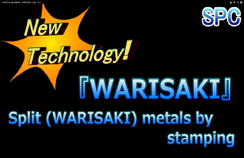
This is a promotion video shows our news technology WARISAKI.
We acquired domestic patent and applied for Taiwan Patent.
How would you use this technology?
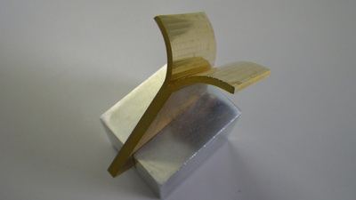
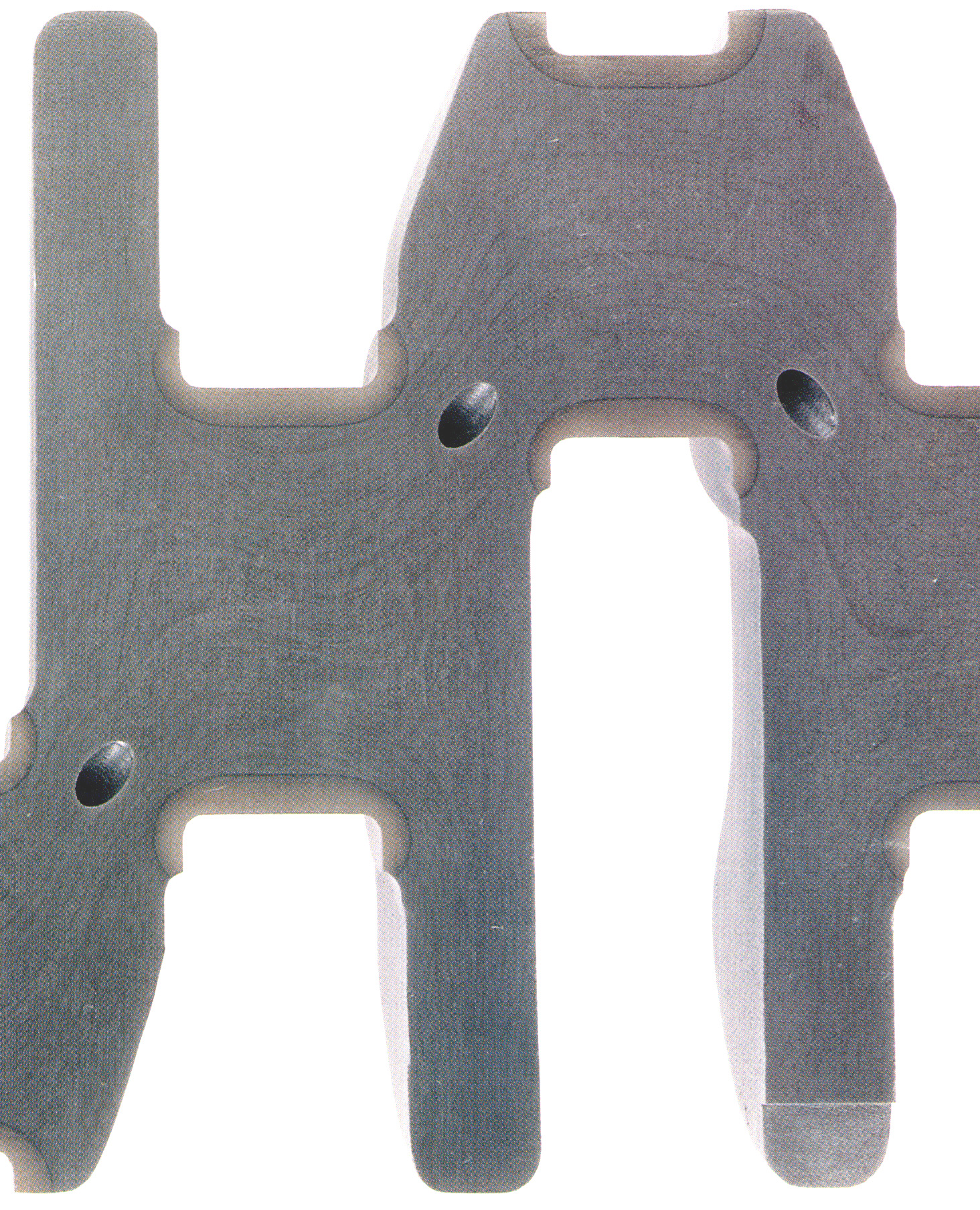
We have succeeded in splitting a plate of brass.

We produce T-shape bracket only by Press processes.
meterials available: Copper, Aluminum, Steel, Brass.
** the reference photo is Steel and Brass.

We succeeded in splitting Stainless steel (punching metal) by WARISAKI press work.
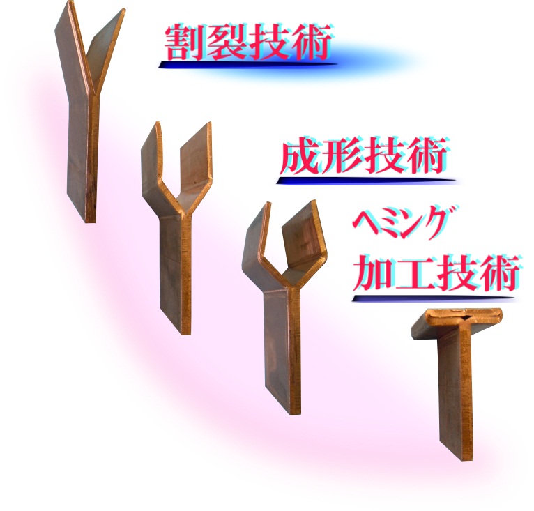
This is the world’s first technology to succeed manufacturing the product from splitting technology (Patent No. 5165806, International and Taiwan patent pending) to Heming processing in the progressive die. It achieved the shortening of the lead time and reducing the cost from the conventional construction method.
Materials: Steel, Aluminum, Copper
It has various uses
・Complex 3D shapes by splitting and hemming
・Jointing dissimilar metals
・T-shape brackets
The Splitting technologies of the titanium and the stainless steel are now on trial.
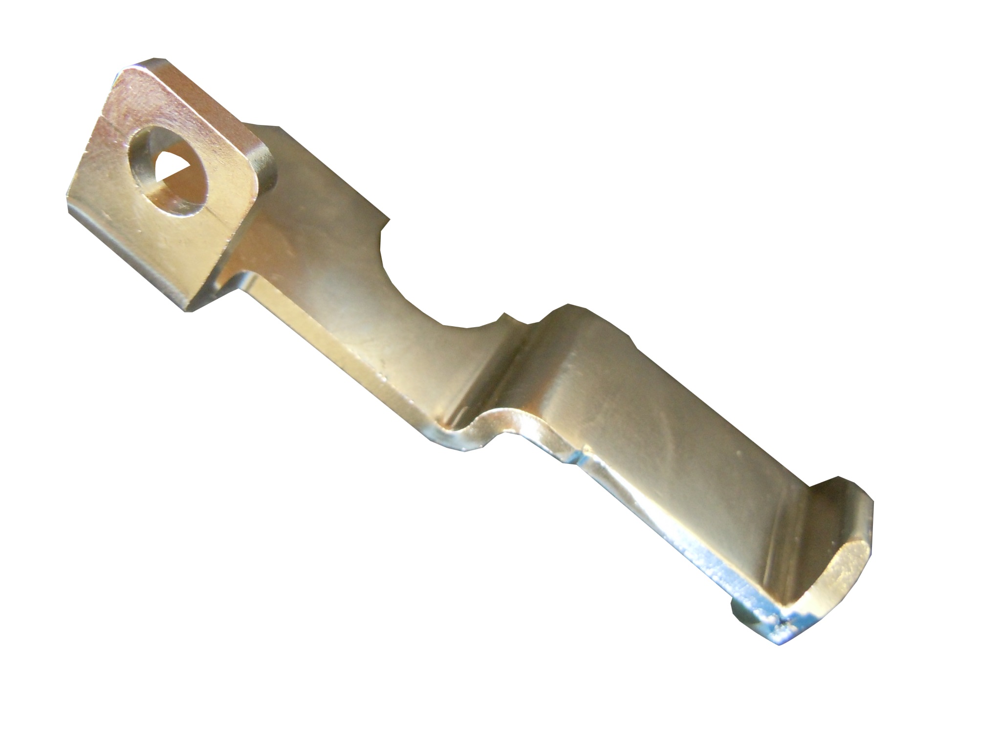
We utilized splitting (Warisaki) processing technology and succeeded to manufacture integrated cast processing products of complicated 3D shapes by the metal press.
・Shifting from previously manufacturing by welding and forging to now process by products by the metal press enabled us to
1) Reduce cost (maximum of 75%)
2) Shorten the lead time (by one quarter)
3) Greatly improve the quality stability due to no connection such as the welding construction method
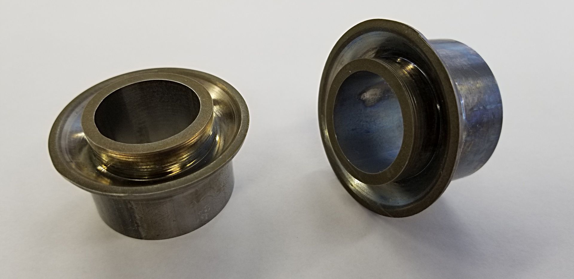
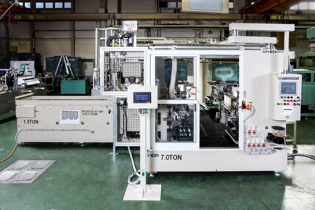
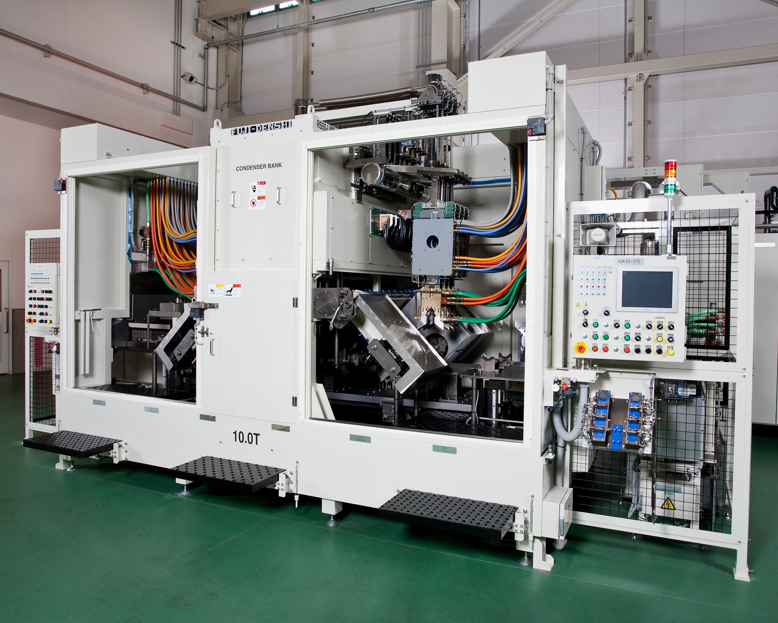
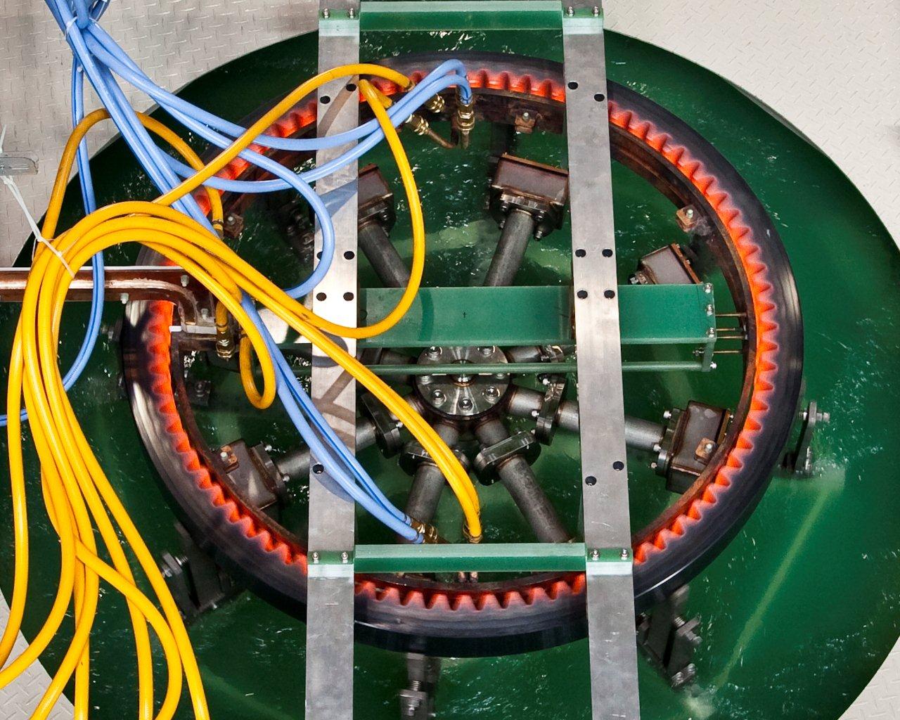
ONLY ONE Processing Technology [Outer Perimeter Split Method]
Forms a three-dimensional shape from an electric resistance welded tube.
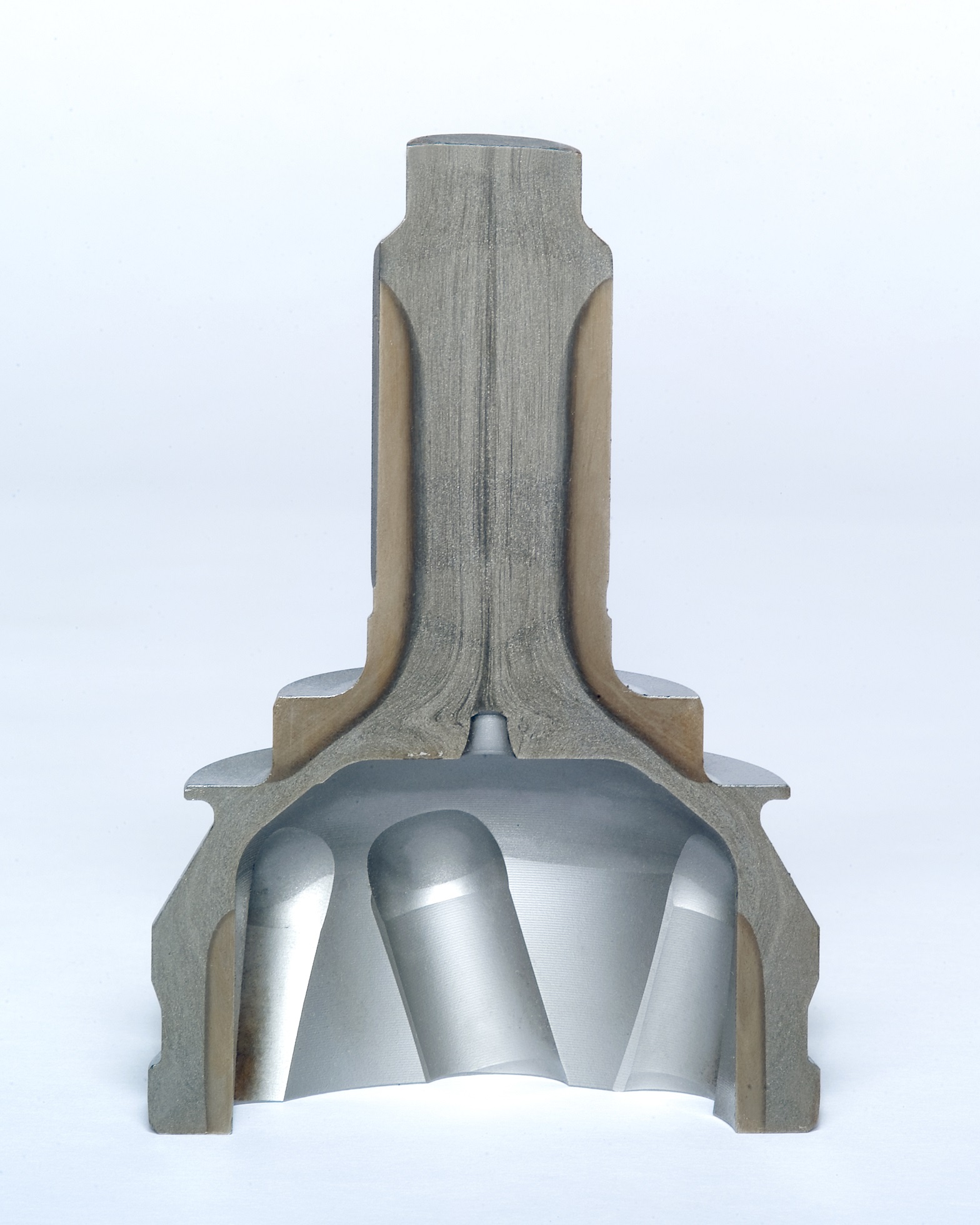
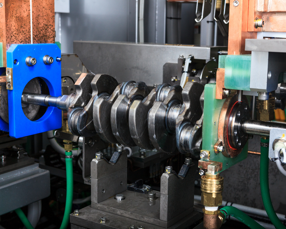
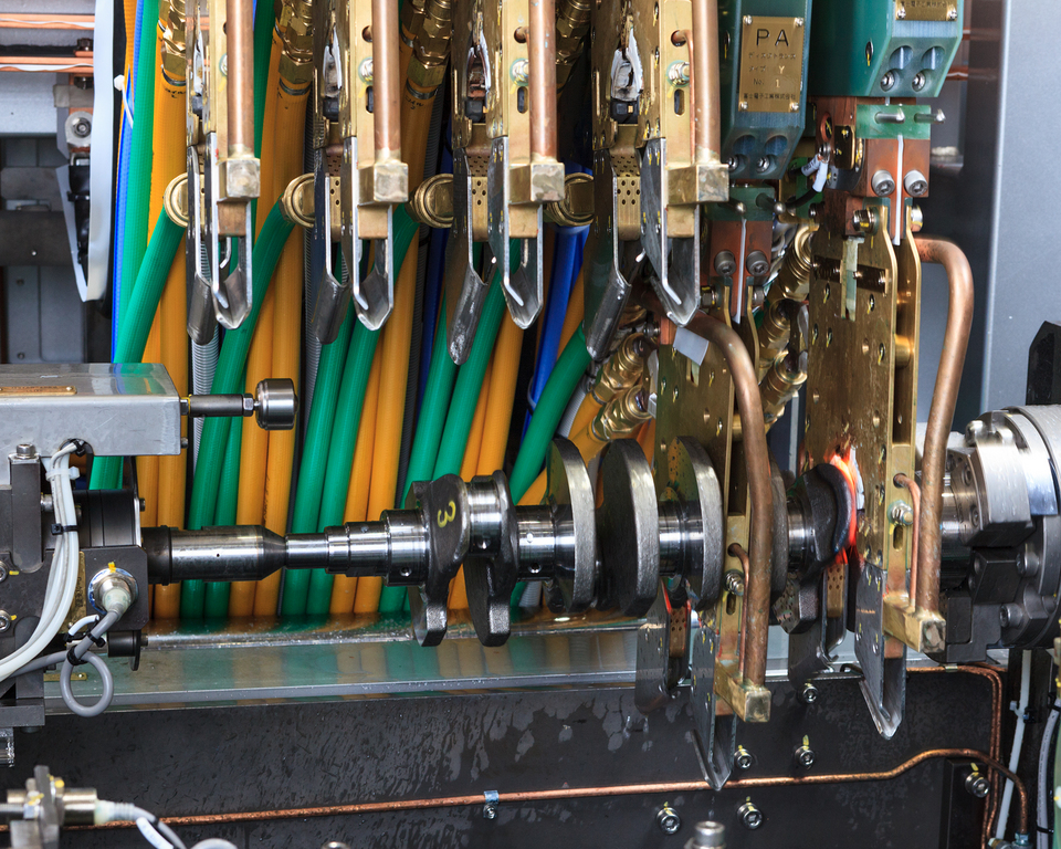
This product is a type of crankshaft quenching used in automobile engine parts.
Fuji Electronic Industry owns 80% of the share market in Japan with accumulated knowledge to challenge to new technologies.
Our crankshaft quenching is processed through a unique method called Elothrm method.
We have an established technique for the quench pattern (R quenching) which can be seen in this picture and will be glad to suggest applying to customer’s products.

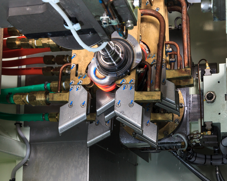
The product shown in the picture is a cut sample of a small diameter precise ball screw.
The bottom (diagonally right) product has been processed using an ordinary quenching technique.
The top (center) product’s appearances are exactly as before processing.
However, inner portion is quenched completely.
As one can see, our “non-oxidation quenching” will not cause any scale as ordinary quenching.
This method requires no after treatment as shot blast.
In other words, scales and sands which can cause reduction of after treatment preciseness will not be problematic.

We sale high frequency induction heating machineries.
This machine will utilize the induction heating principle which has effects on improving surface hardness and improved wear resistant.
【Advantages of the Induction Heating Quenching】
・Shorter lead time → Reduced processing steps
・Efficiency → Lower electricity usage, aka energy saving
・Heat when needed → A small lot manufacturing
・Partial Quenching → Partially quench depending on the shape
・Only require electricity → Ecological (no smoke and/or gas emission)
・The product will generate heat → Heat efficient
・Easy to in-line
In addition, our manufacturing section produces products on commission.
Also gladly handle a small lot orders, complicated shapes, and/or first time quenching for the specific product.
Feel free to contact us.
We have achieved to establish simultaneously and automatic cam quenching which can manufacture 240/h and 3600 sections resulting in overall cost reduction.
For those work which each cam and journal are placed side by side, by using our uniquely produced outlet ring, the ring will insulate any effect towards unnecessary parts.
Also, by adjusting bearing and cam, other types and shapes of camshaft can be processed.
We will gladly support prototyping, quality inspection, equipment installation, and maintenance of equipments after installation.
*Please consider us for prototyping, manufacturing by commissioning, and buying equipments.
Picture:Double Quenching. Cycle time 1:27 per 2.
Hands on and off model.
In house assembled oversize carburizing machine.
[Main Product] Bearing race, large size internal gear, large size gear
✔ Max. φ1800×(H)400mm
[Material] Carbon steel (S45C), Stainless steel (SUS304)
[Single Quench]
For transfer quenching, starting and ending point of heating and cooling overlaps leading to cracks or reduced hardness.
With Fuji Electronic all around single shot quenching, a complete uniformed quenching layer can be produced even a slewing ring size of diameter of 1.8m and module of 15. Also, comparing to transfer quenching, improved productivity, 1/5 work speed, and 1/2 ~ 1/3 electricity consumption.
[Carburizing]
Once the heating process has completed, by simultaneously dipping the product into the cooling water and blasting water current through jackets, helps to prevent from entering while forming a uniformed quenched layer.
In addition, by controlling quenching water temperature and stir speed, an effect layer can be controlled precisely.
[Inner and Outer Diameter Simultaneously Heating]
By having two electrical switches on both sides, the inner and outer layer can be quenched simultaneously with low distortion.
-415
A high frequency quenching with a numerous track records in multi turn coil.
By applying a high frequency electrical current evenly to place where quenching is required in an inner groove, a deep uniformed quenching layer can be formed without any overheating, melting, or temperature differences.
A central coil quenching provides plentiful quenching depth for R while leaving no uneven quenching depth, uneven depth quenching, or burn deformation behind,
Since our coils are highly functional, highly durable, and highly precise, meaning, overall running cost can be reduced through less coil repair cost, less electricity usage amount, and less quality inspection process after coil exchange.
TY
-464
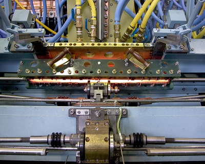
【Ordered Equipment】Drive Shaft Induction Quenching Equipment
[Future]
①A single unit production 225 per an hour.
②Compared to a movable induction quenching machine, a single shot system is 40 ~ 50% energy savings.
③40% better diameter ratio of induction quenching depth, resulting in improved fatigue strength.
④Less than 1/1000 of max length bending and low distortion treatment is applicable.
IT
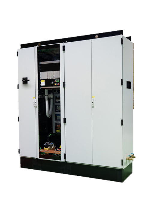
We manufacture induction heating machines and do job heat treatment.
This photo shows our originally developed induction heating converter FOCUS.
Manufactured entirely in-house from design to assembly,
we supply our customers with domestically made, guaranteed products.
Conversion efficiency is top class in the industry at 95%
and contributes to energy and cost savings.
~Induction Hardening Converter Development~

Fuji Denshi's crankshaft hardening utilizes the Elotherm method,
heating the rotating workpiece with a semi-open coil.
Design and manufacturing of high quality crankshaft hardening
machines requires advanced technology.
After implementing this advance method from early on,
it has been regarded worldwide and established a vast track record.
Fuji Denshi was selected as a Global Niche Top Company 100 in 2013.
Feel free to send all your inquiries about hardening and other heat treatments to us.
~Osaka Fuji Electronics Industry Crankshaft Hardening Machine~

[Fuji Denshi Job Heat Treat Plant]
The large dip-quench hardening machine installed in our job heat treat plant
is mainly used for large gears and rollers.
It can treat parts up to 1.8m in diameter.
The photo shows the dip-spray process in action.

At Fuji Denshi, we design, manufacture, and sell induction heating machines
as well as do job heat treatment and prototype development.
The photo shows our stub shaft axle hardening and reheating machine.
The one-shot hardening method using our line coil achieves an ideal case
pattern even with the varying diameter of the workpiece, while saving energy.
The entire length of the workpiece is quenched simultaneously,
ensuring the residual heat over the part's length is even and
preventing cracking and uneven case hardness and depth.
(Even heating / Even quenching)
Heating and quenching are both even over the entire surface,
so runout is kept at a minimum even without the need for a straightening roller.
The residual stress along the axle axis contribues to large increases
in the part's durability and strength.
(2x by comparison)
Scan hardening can easily cause uneven hardness and low axial strength.
Our one-shot hardening requires only half the power of scan hardening to better results.

[Fuji Denshi Job Heat Treat Plant]
The small dip-quench hardening machine installed in our job heat treat plant
is mainly used for gears, rollers, and bearing races.
It can treat parts up to 0.65m in diameter.
Larger parts are treated with our large dip-quench hardening machine.
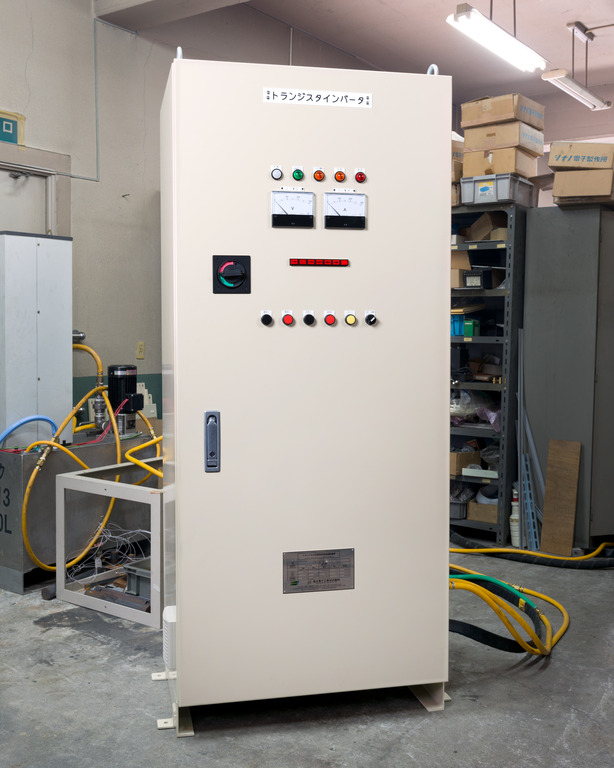
We recently introduced our originally developed compact transistorized converter, FIT.
FIT is suitable for low power applications such as hardening, heating, and brazing.
Continuing in the line of our FUJI-ELOMAT converter, the new FIT
is a less expensize option.
The high conversion efficiency results in at least a 55% decrease in power consumption
and 75% decrease in running cost compared to vacuum tube converters.
Our FIT converter is suited for various application including brazing.
We await your inquiry!
The photo shows a cut sample of an automobile engine camshaft hardening by our original machine.
At Fuji Denshi, we developed the eccentric hardening method for camshafts.
The coil follows the rotating cam in an eccentric pattern, achieving an
even casing and stable residual stress over the whole cam.
Cracking on the nose from overheating and post-grinding are prevented for high productivity.
The photo shows a cut sample of an automobile powertrain lebro joint
(cross groove universal joint) whose outer has been hardened by our machine.
We used our original SMT coil for lebro joint and BJ outer inner surface hardening.
By one-shot hardening the rotating workpiece, an ideal casing is achieved.
The stem section is hardened by single shot hardening using our specialized semi-open coil.
This method achieves an ideal hardened pattern along the outer diameter all the way to the corners while maintaining high productivity.
At Fuji Denshi, in addition to our specialized hardening and reheating processes,
we also perform post-processing.
Our shot blast machine is mainly used for shaft post-processing and can process
rod-shaped parts up to 780mm in length.
Leave your post-processing needs to us.

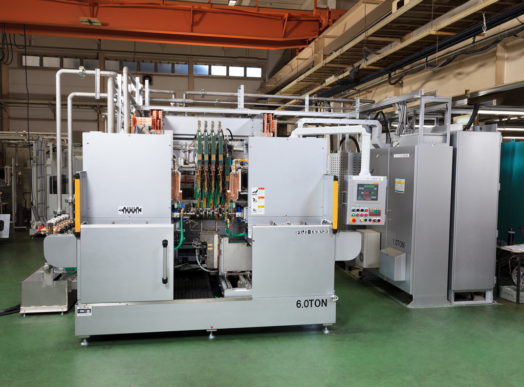
We design and manufacture crankshaft hardening machines.
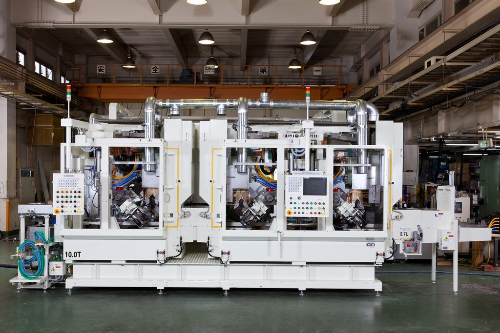
The photo shows an automobile V6 engine crankshaft induction hardening and reheating machine.
This machine is installed in-line at an engine plant.
It receives the workpiece from the previous process, performs hardening
automatically, and sends the workpiece to the next process.
The workpiece is loaded from the port on the right.
First the pins are induction hardened at the right and center stations,
followed by the journals at the left station.
Finally the work is unloaded from the port of the left.
This machine performs flat hardening, which in general is a simpler process,
but to achieve the specified short cycle time of under 50 seconds,
the machine was designed with two converters and three hardening stations
for high productivity.
The photo shows the hardening and reheating stations in a automobile propeller
center bearing shaft induction hardening and reheating machine.
On the right with the green spray quenching jacket is the hardening station.
On the left in the brown box is the reheating station.
※At Fuji Denshi, we refer to tempering as reheating to differentiate from
furnace methods.
The hardening and reheating stations are divided and have separate converters
to achieve a cycle time of under 30 seconds.
This design achieves both compactness and high productivity.
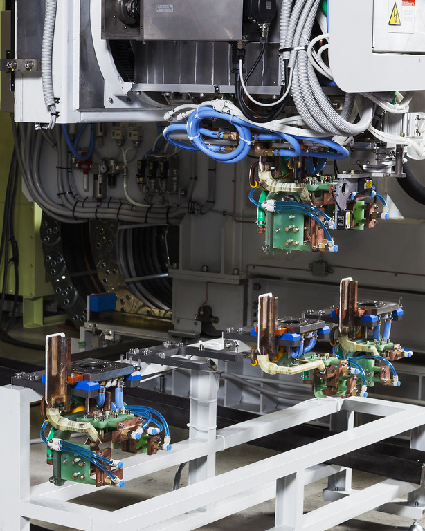
Fuji Denshi's camshaft hardening machine uses our patented eccentric
tracking mechanism.
The coil follows the rotating cam nose to achieve even heating.
Using these technologies, cracking during grinding is prevented
while achieving an even casing and low runout.
The high-speed design also contributes to shorter cycle time.
The photo shows our production machinery bed hardening machine during
automatic coil changing.
Our bed hardening machine's automatic coil changer reduces retooling time
and necessary work.
In the photo, the previous coil is returned to the coil station and the changer
picks up a new coil.
Our gate model bed scan hardening machine is the first machine in the world
to be installed with this device.

We manufacture driveshaft induction hardening machines.
[Machine Features]
① High productivity of 225 parts/hour
② Single shot method for 40~50% energy savings versus scan hardening
③ Case depth of over 40% of diameter to achieve high fatigue strength
④ Originally developed straightening roller to prevent run out during hardening
Please contact us for your questions and concerns about driveshaft hardening.
~Driveshaft Induction Hardening High Productivity Energy Savings
Fatigue Strength Low Runout~
This is our crankshaft induction hardening machine, able to treat crankshafts
for automobiles, agricultural machinery, construction machinery and more.
The machine can be adapted for a variety of crankshafts by
retooling the coil and jigs and other adjustments.
It is also able to perform hardening of split pins for V engine crankshafts.
With manual loading/unloading, after placing the workpiece on the front left jig,
the jig moves to the center and carries the workpiece to the back
of the machine.
In the back station, the pins and journals are hardened.
If the front station, the crankshaft oil hole section is hardened.
After hardening, the work are carried to the center and unloaded to the right.
While being extremely flexible, this machine also has high productivity.
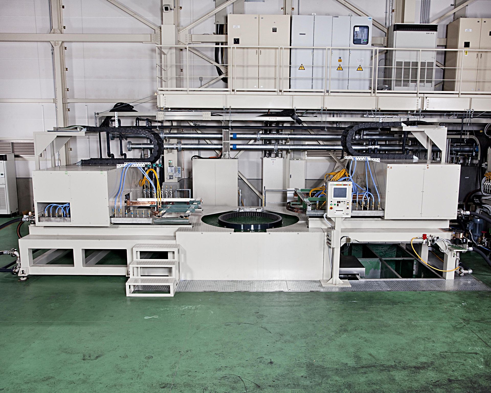
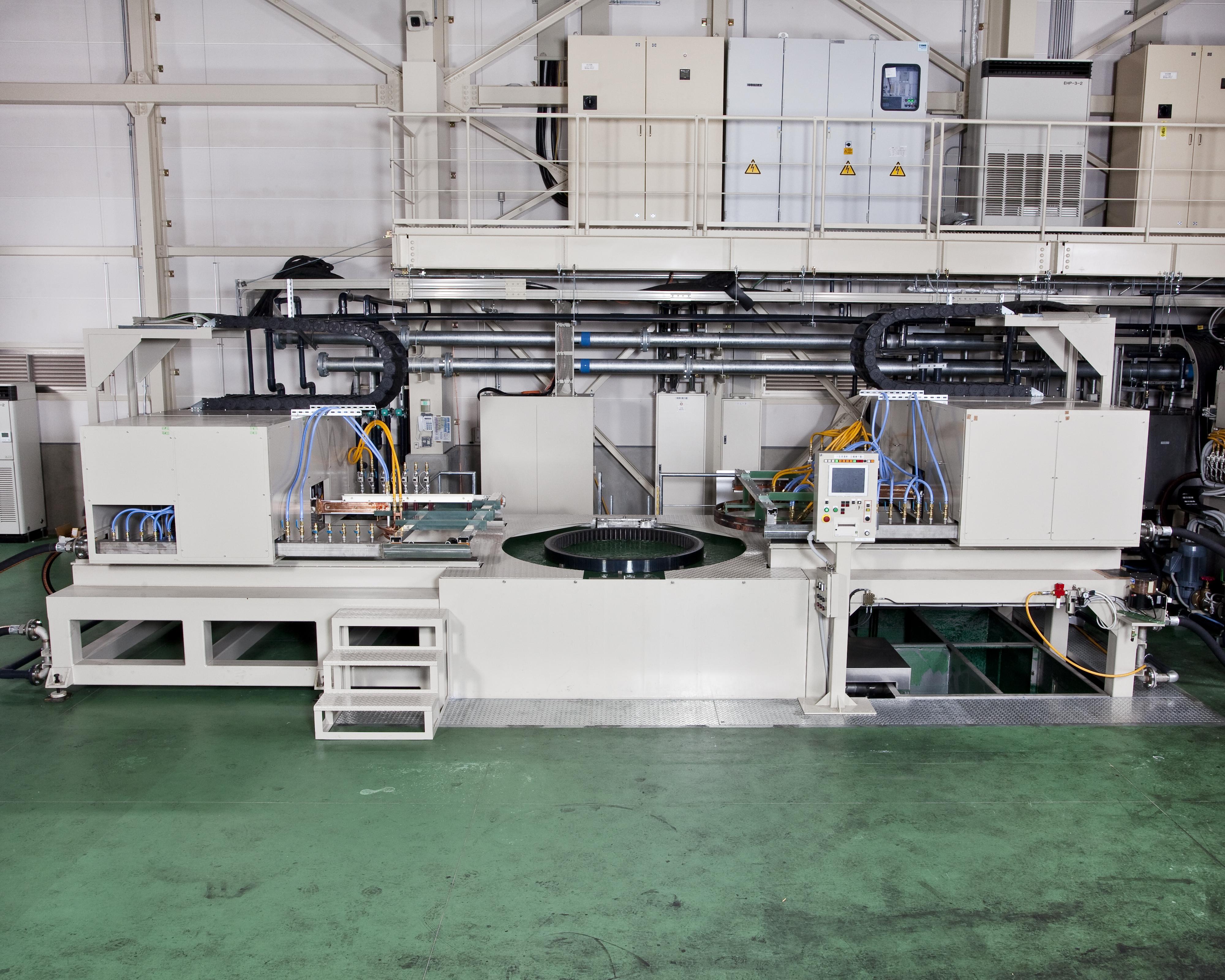
This large dip quench induction hardening machine is installed
in our job heat treat plant.
Outer ring hardening: up to 1800mm diamater, 350mm thickness
Inner ring hardening: up to 1500mm diameter, 150mm thickness
This machine performs one-shot hardening for large gears,
bearing races and more up to the above dimensions.
For gear hardening, this machine features
- even heating by ring coil
- even quenching by dip spray
to minimize runout and cracking.
By heating in two stages, preheating and main heating,
the case depth is deep even in the gear grooves.
Please contact us with your job heat treatment needs.

We manufacture bed induction hardening machines.
The pictured hardening machine is for industrial machine beds.
Our bed hardening machine features our automatic coil tracking system,
which maintains the gap between the coil and workpiece
by sensor during the automatic hardening process.
As seen in the photo, the extremely small gap between the coil
and workpiece is maintained throughout the process.
The power consumption by the workpiece is highly efficient,
while achieving an even casing, ensuring high quality and energy savings.
~Bed Hardening Machine Induction Hardening Machine
Industrial Machine Machine Tool Parts IH Heat Treat~

[Job Heat Treatment]
The photo shows our custom-made large dip quench hardening machine.
[Major workpiece types] bearing race, large internal gear, large gear
※ Outer diameter: up to Φ1800, thickness 350mm
※ Inner diameter: up to Φ1500, thickness 150mm
[Material] steel (S45C), stainless steel (SUS304), etc.
[One-Shot Hardening]
During scan hardening, the beginning and end points are heated
and quenched twice, which can cause cracking or soft spots.
In contrast, our one-shot hardening achieves a sufficiently deep casing
around the whole circumference of gears up to 1.8m diameter and 15 module.
[Dip Quench Hardening]
Immediately after heating, the workpiece is submerged in quenching water
and sprayed by quenching water jackets. This prevents the formation of
an air layer around the workpiece and ensures an even casing.
By controlling the water temperature and mixing speed,
the resultant casing can be controlled to high precision.
[Inner/Outer Simultaenous Heating]
The machine can be fitted with two power sources to heat the
inner and outer surfaces at the same time.
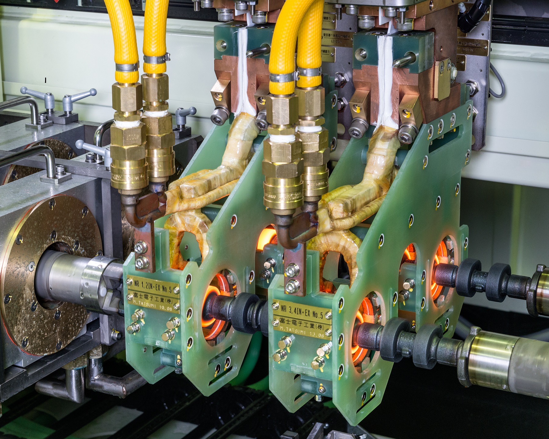
This photo shows out automobile engine crankshaft induction
hardening machine.
This machine is installed in-line at an engine plant.
It receives the workpiece from the previous process,
performs hardening automatically, and sends the workpiece
to the next process.
The workpiece is loaded from the port on the right.
First the pins are induction hardened at the right station,
followed by the journals at the left station.
Finally the work is unloaded from the port of the left.
This particular machine is specified for flat hardening of
4-cylinder crankshafts,and shows the common features
of our machines, compactness and short cycle time.
As a result, it has a cycle time of under 45 seconds per cycle
for extremely high productivity.
[Custom-made Machines]
This is the flange oil seal hardening station of our all-purpose crankshaft
hardening machine, which treats crankshafts for automobiles,
agricultural machinery, construction machinery, and more.
The machine can be adjusted for various types of crankshafts
by exchanging and repositioning the coils and jigs.
In the photo, the flange section of the crankshaft is induction heated
by a ring coil.
The coil is housed in green resin insulation to prevent induction
of the surrounding machine,while the coil is cooled by a continuous flow
of cooling water through its copper piping.

The photo shows the hardening station of our all-purpose single axle
double bed vertical scan induction hardening machine.
Our vertical scan induction hardening machines typical move the coil
during scanning, but this machine was designed for the workpiece
to move as specified by our customer.
The machine also can perform one-shot hardening, as seen in the photo.
The coil heats the workpiece from above and the jacket quenches it from below.
By rotating the workpiece while heating with our line coil, the multi-diameter
workpiece is heating along the whole circumference.

[Job Heat Treatment]
The photo shows the shaft hardening machine in our job heat treatment plant.
The left- and right-hand station are independent, allowing for treatment of
different workpieces.
Shafts from diameter 14~17mm and length 145~180mm can be treated.
Please contact us for your job heat treatment needs.
The photo shows our automobile engine camshaft induction hardening
and reheating machine.
To increase productivity, the machine was designed with two stations,
which alternate between hardening and reheating using one converter.
※At Fuji Denshi, we refer to tempering as reheating to differentiate
from furnace methods.
Loading/unloading is done manually. After placing the workpiece
on the front right side jig, a robotic arm carries it to each station.
After hardening, the arm carries the workpiece to the front left port.
This machine also features our patented coaxial coil lead which has
lower lead power loss. The coil lead is shielded from the induced current,
resulting in longer coil life.

The photo shows the heating station of our automobile engine
camshaft induction hardening and reheating machine.
3 coils are used to simultaneously heat 6 cam noses of a V6 engine camshaft.
Our original coil design prevents cracking from overheating of the cast iron camshaft.
The quenching water volume is also controlled to further prevent cracking.
~Camshaft Induction Hardening Reheat Machine②~
As the demands for lighter, stronger, more efficient, and more eco-friendly
engine manufacturing increase, we at Fuji Denshi have supplied over
250 crankshaft hardening machines domestically and overseas.
Our crankshaft hardening technology, based on our semi-open coil
and rotating tracking method, includes numerous innovations which combine
to minimize runout.
Our fillet hardening technology has become a must-have for stonger
and lighter crankshafts.
We strongly encourage manufacturers currently using carburization
to consider our induction technology to improve cost, lead time, and runout.
[Job Heat Treat]
The photo shows hardening of the teeth of a gear.
After heating, the workpiece is lowered into the quenching water,
where it is sprayed by additional quenching water to achieve an even casing.
We have a large-scale and small-scale dip-spray hardening machine
in our heat treat plant, which together can treat parts up to diameter 1.8m.
We have also manufactured and installed this same machine in our customer's plant.
The photo shows the hardening station of an automobile engine crankshaft
induction hardening machine.
During hardening, the coil follows the pin section of the rotating workpiece
as it heats.
※ As seen in the photo, each pin, out of phase with the others,
is treated by a separate coil.
Through this method, our hardening technology is able to achieve:
・low runout
・even casing
・short cycle time
・compact machine design
In recent years, crankshafts have become smaller and thinner to
improve fuel economy.
The pictured crankshaft is a small, thin model, which also required
fillet hardening of the pins and journals.
Using our extensive designing know-how and hands-on experience,
we achieved the specified fillet hardening by designing the coils to
optimize power control.
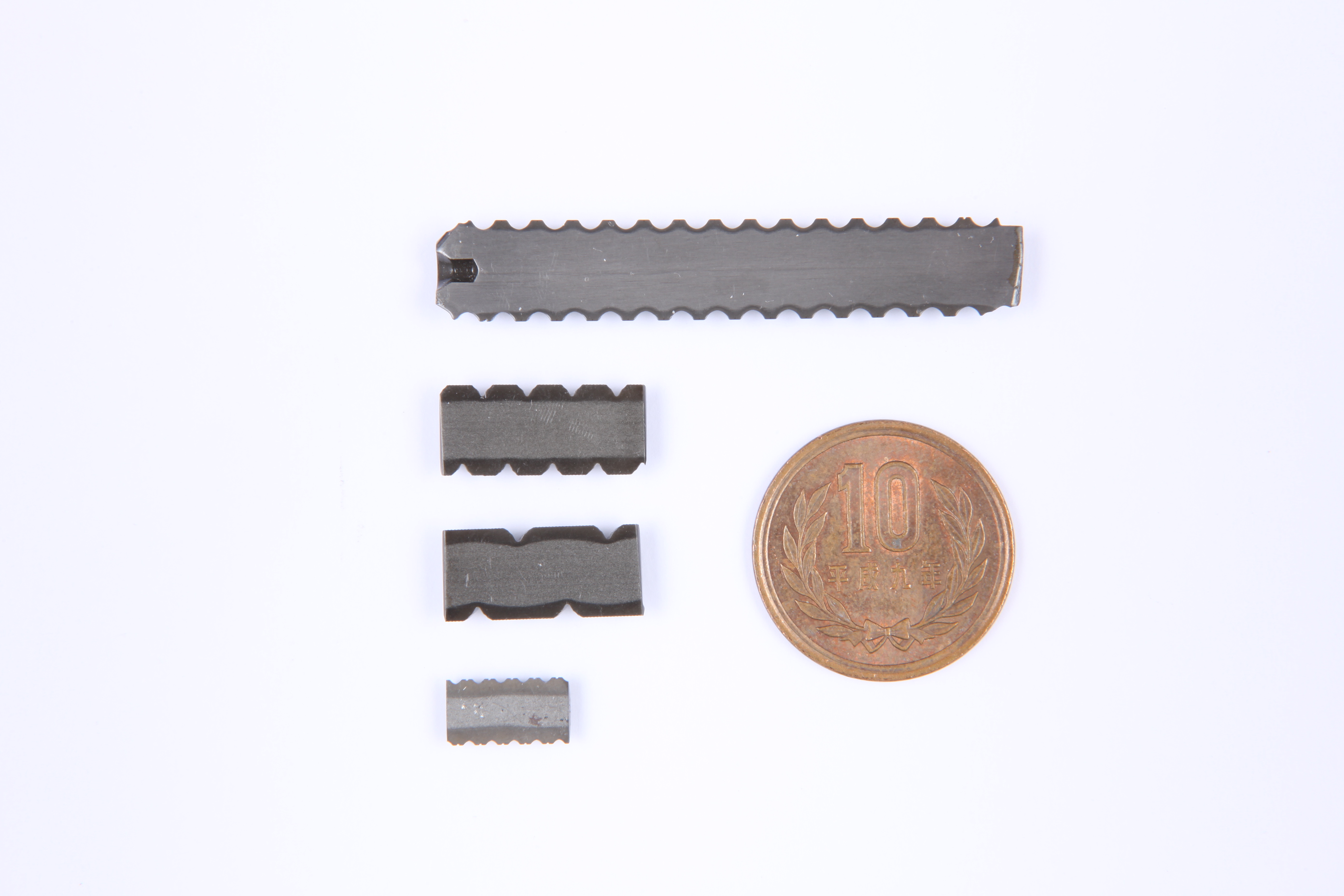
The photo shows a cut sample of a small diameter ball screw,
shown in comparison with a 10-yen coin.
Our method achieves an adequate case depth in the ball groove
without overheating even for small ball screws.
We design each coil custom-made and calibrate each machine
to meet our customer's specifications.
Please contact us with your induction heat treat needs.
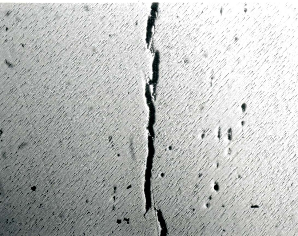
For our customers facing induction hardening cracking, let us at Fuji Denshi
resolve your issues.
● Magnetic Particle Testing
A non-destructive inspection method applicable for surface cracks,
forging cracks, hardening cracks of magnetic materials.
● Principle of Magnetic Particle Testing
Similar to magnetizing a nail by winding it with a conducting enamel thread,
the workpiece to be inspected is magnetized. If there are cracks,
each side of the crack will have opposite polarities.
By applying colored or flourescent iron powder liquid to the workpiece,
the powder accumulates in the cracks, making them visible.
● Demagnetization
After inspection, the workpiece must be premagnetized before post-
processing such as grinding.
At Fuji Denshi, our veteran technicians use our magnetic particle testing
equipment to locate cracks undetectable by color spray.
Please contact us with your concerns about cracking.
~ Induction Hardening Cracking Magnetic Particle Testing ~
The picture shows the pin and journal hardening station of our
all-purpose crankshaft hardening machine, which treats crankshafts
for automobiles, agricultural machinery, construction machinery, and more.
The machine can be adjusted for various types of crankshafts by
exchanging and repositioning the coils and jigs.
During hardening, the workpiece is rotated and the coils follow the
eccentric motion of the pins.
※ As seen in the photo, two pins out of phase with each other are each
followed and heated by a coil.
Through this method, our hardening technology is able to achieve:
・low runout
・even casing
・short cycle time
・compact machine design
Developed based on our extensive designing know-how and hands-on
experience, our heating coils are guaranteed for 20,000 shots.

Shinshu Yoshino Electric specializes in in-house production of metal press and injection molding dies, providing a seamless process from prototyping to mass production.
We have accumulated extensive expertise by working with a wide range of companies, addressing various manufacturing challenges.
With our contract manufacturing services, we offer solutions based on our accumulated processing know-how to help resolve your concerns.
Feel free to contact us for a consultation.
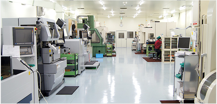
We specialize in mirror-finish machining of iron and steel using a 5-axis machining center. Our primary focus is mold component manufacturing.
Specifications:
Size: MAX 220mm × 220mm × 100mm
Production Volume: 1–10 units/day
Production Lead Time: 1–2 months
Additionally, we manufacture machined components for industries such as office automation (OA) equipment.
For machining services, please contact Shinshu Yoshino Electric.
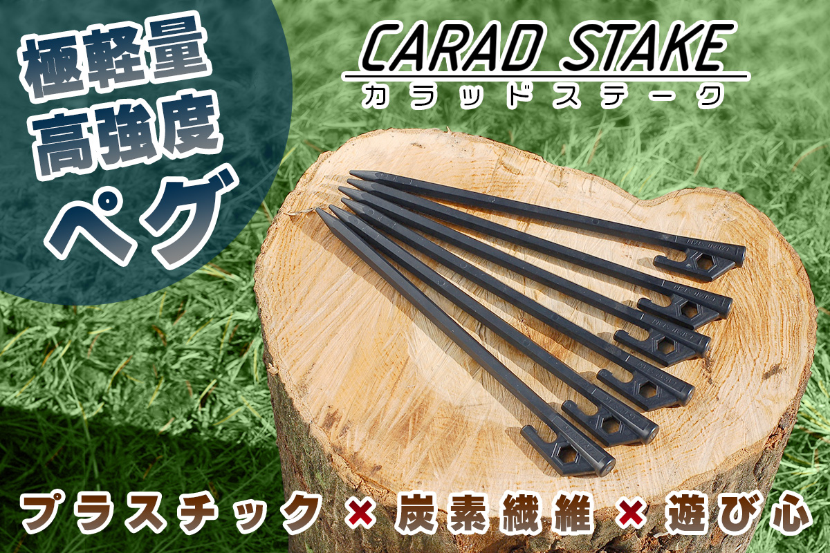
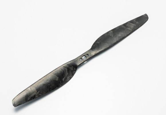
Introducing the CARAD STAKE, a carbon fiber-reinforced plastic peg that achieves ultra-lightweight and high strength.
We are pleased to announce that general sales have begun. We would be delighted if you take this opportunity to try the CARAD STAKE. Please refer to the links below for purchase details.
1. Gulliver Online Shopping (Rakuten Store)
https://item.rakuten.co.jp/glv/crd-00000-jp/
2. Shinshu Yoshino Electric Official Website Shop (STORES)
https://sincere-tee.stores.jp/
This product is made using our unique Direct Fiber Injection Molding Method for CFRTP (Carbon Fiber Reinforced Thermoplastic) molding.
Material Composition:
The primary material is PA-based GF-reinforced material, with additional carbon fiber (CF) for further enhancement.
(CF can also be added to materials other than PA-based plastics.)
Compared to general long fiber pellets (LFP), our molding process ensures longer fiber retention within the molded product, resulting in a higher aspect ratio and increased strength.
Additionally, in-house compounding allows us to offer cost reduction proposals.
Product Details:
Size: 20mm × 15mm × 150mm
Production Volume: 1,000 units/day
Production Lead Time: 1.5–2.5 months
We also manufacture a variety of products for industries such as office automation (OA) equipment.
For insert molding and press processing, please contact Shinshu Yoshino Electric.
We specialize in electronic device components for the automotive industry.
Our insert molding process utilizes materials such as PBT (Polybutylene Terephthalate) and PPS (Polyphenylene Sulfide).
Production Process:
Resin & press mold design & manufacturing
Press component processing
Insert molding
Product Specifications:
Size: 30mm × 40mm × 20mm
Production Volume: 5,000 units/day
Production Lead Time: 1.5–2.0 months
Additionally, we manufacture a wide range of products for industries such as office automation (OA) equipment.
For insert molding and press processing services, please contact Shinshu Yoshino Electric.
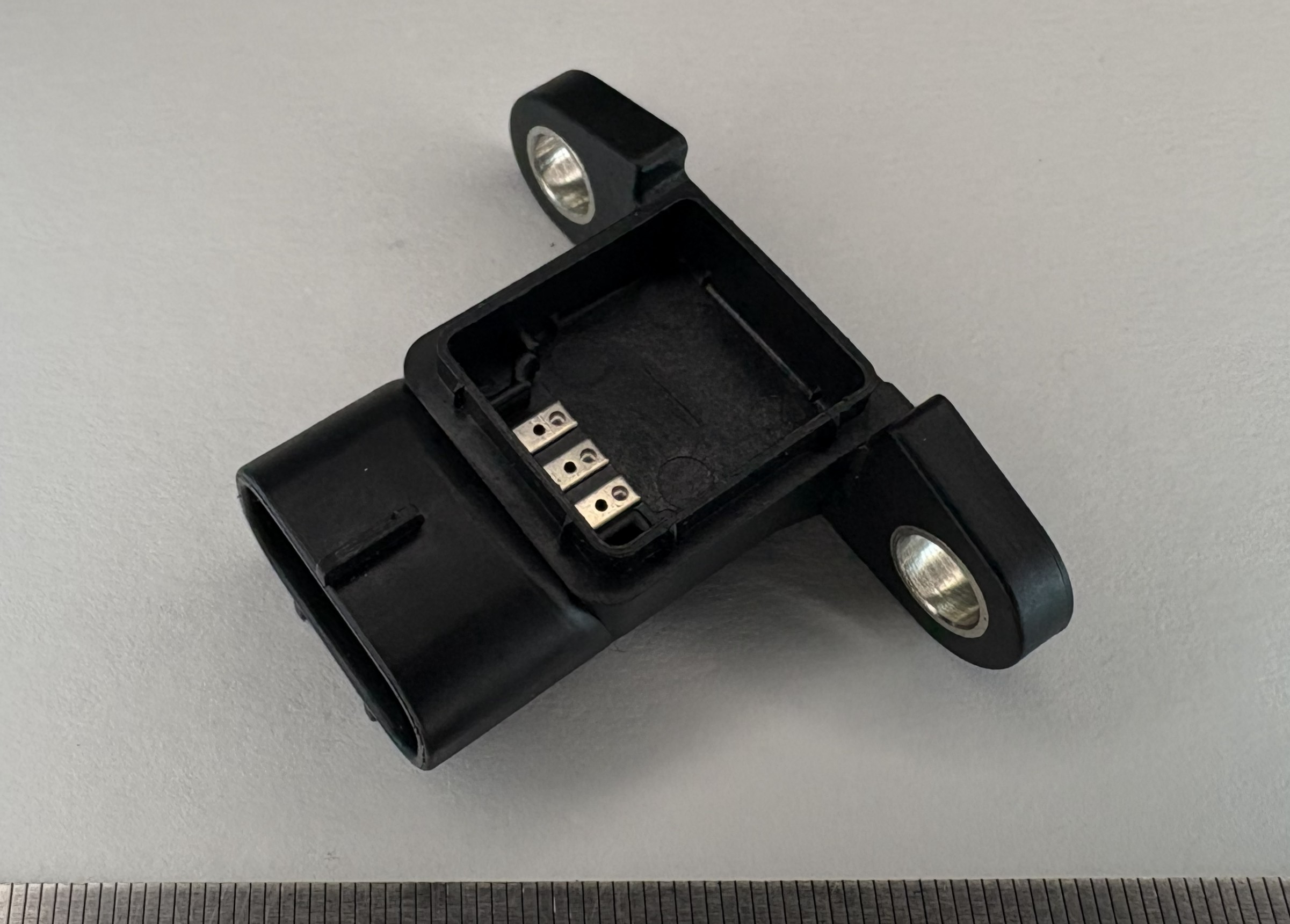
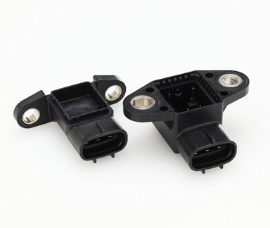
The photo shows an electronic device component developed for the automotive industry.
This insert-molded connector is manufactured using the following materials:
Resin: PBT
Terminals: Phosphor bronze
Pipe: Fe (steel)
Leveraging our expertise in the design and manufacture of press dies and engineering plastic molds, we provide fully integrated, in-house production—from terminal press processing to insert molding—within a single facility.
IATF 16949 Certified
For stable, high-volume production of automotive components, trust your requirements to us.
“Technology, Perfected.”
Shinshu Yoshino Electric Co., Ltd.
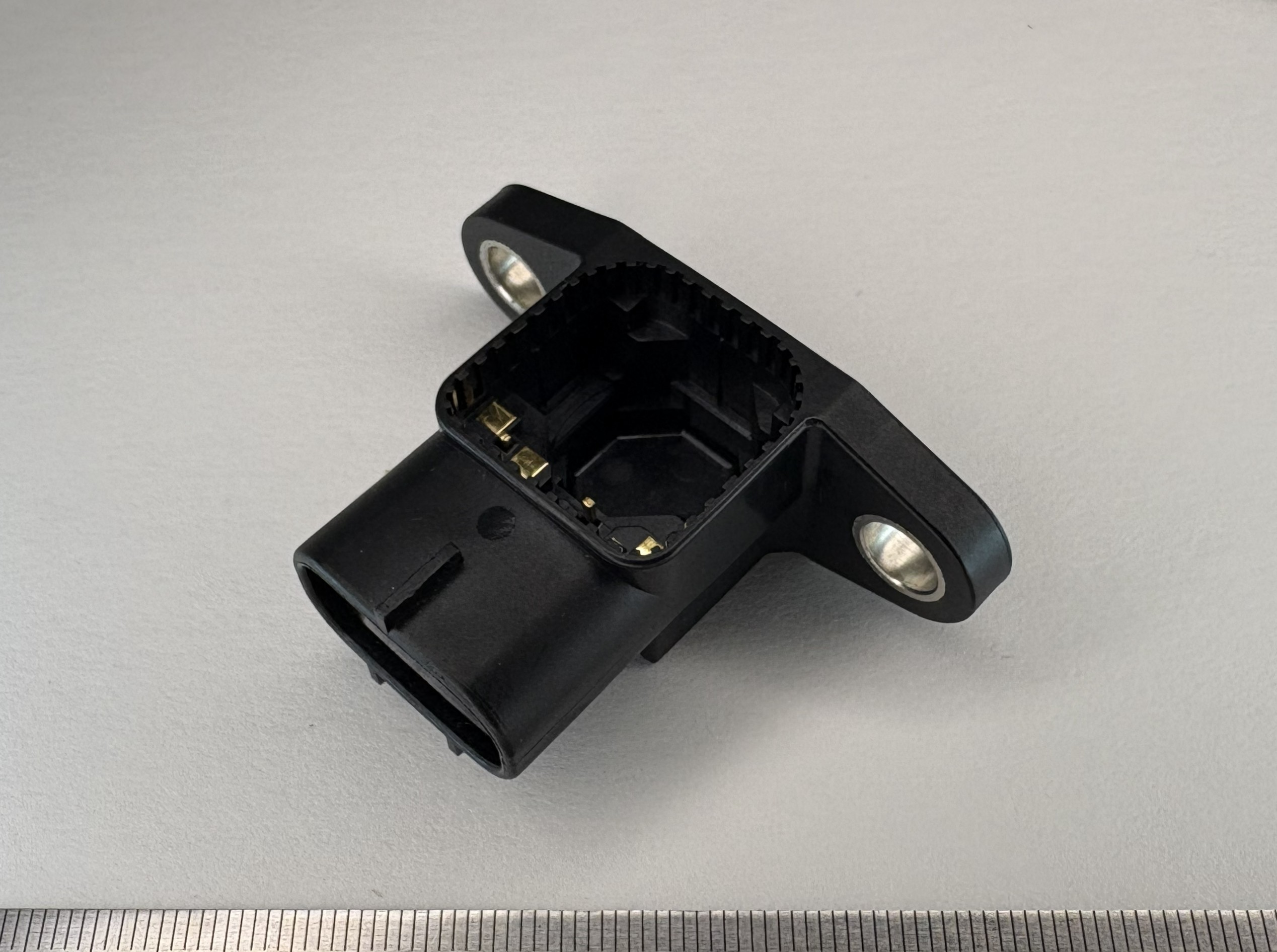
The photo shows an electronic device component designed for the automotive industry.
This insert-molded connector is manufactured using the following materials:
Resin: PBT
Terminals: Phosphor bronze
Pipe: Fe (steel)
Based on our expertise in the design and manufacture of press dies and engineering plastic molds, we provide fully integrated, in-house production—from terminal press processing to insert molding—all within a single facility.
IATF 16949 Certified
For stable, high-volume production of automotive components, trust your requirements to us.
“Technology, Perfected.”
Shinshu Yoshino Electric Co., Ltd.
【Causes of Unstable Hinge Durability】
Hinges are critical for door and cover operation, but insufficient precision or strength in the rotational shaft can cause looseness, noise, and premature wear.
A key issue is the machining accuracy of the “rolled section” forming the shaft. Roundness, clearance, and material integrity (e.g., cracks or excessive work hardening) directly affect lifespan.
Curl bending is a common method used to form this rolled section.
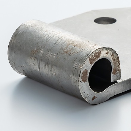
【What is Curl Bending】
〈Plastic forming that rolls sheet material into a cylindrical shape〉
Curl bending rolls the edge of a sheet into a cylindrical shape. In hinges, a pin passes through this section to form a rotational mechanism. Unlike simple L- or U-bends, the material forms nearly a full circle.
The outer surface is under tension and the inner under compression, requiring careful control of:
・Inner diameter
・Bend radius
・Springback
・Material hardness
High precision is essential for smooth, reliable rotation.
【Technical Points for Hinge Curl Bending】
〈Ensuring roundness and coaxiality〉
Hinges combine multiple curled sections with a single pin. Misalignment can cause stiff rotation or assembly issues. Precision is achieved through:
・Accurate hole positioning and outer profile
・Multi-stage forming for load distribution
・Die compensation for post-forming variations
Kawamura Kikai Co., Ltd. operates 50 press machines (10t–500t) and handles deep drawing, bending, punching, trimming, and complex 3D forming like curl bending.
【Process Design to Prevent Cracking and Collapse】
〈Avoid finishing in a single process〉
Forming the cylinder in one step can cause outer cracks or inner collapse, reducing roundness. Solutions include:
・Gradual curling over multiple stages
・Stabilizing the inner diameter with die geometry
・Adding caulking or corrective steps as needed
Multi-stage process design is essential.
【Applications of Curl Bending】
Curl bending is used beyond hinges, in components such as:
・Rotational bearing parts
・Pin-retention brackets
・Clamp components for wiring
・Hinge sections of safety covers
These are functional areas for movement and retention. Shape accuracy directly affects performance and reliability.
【Key Criteria for Considering Curl Bending】
〈Manufacturing difficulty is determined at the design stage〉
Difficulty cannot be judged from drawings alone. Important factors include:
・Sheet thickness vs. inner diameter
・Material ductility
・Required rotational torque and clearance
・Integration with subsequent processes
Considering manufacturability from the design stage ensures stable and efficient mass production.
【Summary】
For hinges and other rotational components, the precision of curl bending greatly affects lifespan and operational feel. It is not just bending; plastic forming technology and proper process design are crucial.
If there are issues like looseness, assembly defects, or new rolled structures are being considered, reviewing the forming method early is highly effective.
【Contact Information】
Kawamura Kikai Co., Ltd.
Head Office: 2-4 Shimizu-cho, Itabashi-ku, Tokyo 【Composite Division】
Hanazono Factory: 10 Kitane, Fukaya-shi, Saitama 【Metal Press Division】
Website: https://www.kawamura-kikai.co.jp
Inquiry / Quotation: https://www.kawamura-kikai.co.jp/contact/
Please mention that you saw us on “Emidas” when making your inquiry.
【Problems with Sheared Surface Quality?】
In press processing, issues such as rough sheared surfaces, large burrs, and the need for secondary machining often occur. For parts related to fitting or sliding, shear surface quality directly affects performance and assembly accuracy. Conventional blanking can create fracture surfaces and dimensional variations, leading to additional grinding or machining.
【What Is Shaving】
〈Finishing after shearing〉
Shaving is a precision shearing method that removes a small allowance after the initial blanking process. By cutting away the fracture surface, the edge becomes almost entirely smooth sheared surface.
Benefits include:
・Smoother shear surfaces
・Improved dimensional accuracy and perpendicularity
・Reduced burrs
・More stable fitting performance
【Importance of Die Design and Press Technology】
Effective shaving requires optimized clearance design, material understanding, cutting allowance, die rigidity, and press accuracy.
Kawamura Kikai Co., Ltd. supports die design, manufacturing, and maintenance in-house, enabling integrated optimization of shearing conditions and die specifications. The company operates 50 press machines (10–500 t) for various press processes.
【Typical Applications】
Precision shearing with shaving is suitable for:
・Gear and ratchet components requiring precise tooth profiles
・Shaft fitting holes needing high roundness and perpendicularity
・Thin precision parts requiring minimal burrs
・Reference holes for welding or riveting processes
Stable shear quality reduces assembly variation and defects, and can minimize additional machining processes.
【Key Considerations】
Although shaving requires more complex die and process design, its value lies in overall process optimization, such as:
・Reducing secondary machining
・Preventing assembly defects
・Improving dimensional stability in mass production
【Summary】
Sheared surface quality strongly affects product performance and assembly.
Precision shearing using shaving can improve edge quality while simplifying the overall manufacturing process. For issues related to burrs, rough edges, or excessive machining, reviewing the forming process may provide an effective solution.
【Contact Information】
Kawamura Kikai Co., Ltd.
Head Office: 2-4 Shimizu-cho, Itabashi-ku, Tokyo 【Composite Division】
Hanazono Factory: 10 Kitane, Fukaya-shi, Saitama 【Metal Press Division】
Website: https://www.kawamura-kikai.co.jp
Inquiry / Quotation: https://www.kawamura-kikai.co.jp/contact/
Consultations on precision shearing and shaving technologies are available even at the early evaluation stage. Please share your processing requirements or technical challenges, and we will propose suitable solutions.
Related URL: https://www.kawamura-kikai.co.jp/product/
【Importance of Horizontal Cutting】
Accurate horizontal trimming ensures proper assembly fit, sealing performance, and surface appearance. Instability can lead to gaps, misalignment in welding/caulking, poor sealing, and inconsistent appearance.
【Press Trimming as a Core Technology】
〈Die design determines performance〉
A press trimming die is not simply a sliding mechanism.
To achieve stable and precise horizontal cutting, advanced design is required, including:
・High-precision mechanism converting vertical motion to horizontal motion
・Sufficient rigidity during cutting
・Proper blade clearance design and durability
・Accurate positioning relative to the formed part
Kawamura Kikai Co., Ltd. has over 70 years of metal press experience, with in-house die design and manufacturing.
They support press trimming as a core technology for mass production up to t = 1.6 mm, including integration into transfer press lines.
【Equipment and Processing Capabilities】
The company operates 50 press machines ranging from 10 to 500 tons, supporting a wide range of processes including drawing, bending, blanking, trimming, caulking, and spot welding.
Press trimming is particularly effective for:
・Horizontal trimming of drawn openings
・Side trimming of cylindrical components
・Parts requiring strict height accuracy
・Edge finishing prior to welding
With in-house die manufacturing, rapid optimization of trim height and blade geometry is possible during prototyping, while also ensuring durability and maintainability for mass production.
【Comparison with Other Methods】
〈A mass-production solution without machining〉
Horizontal cutting of sidewalls can also be achieved through machining processes
such as turning or milling. However, for mass production, these approaches introduce:
・Increased processing time
・Higher fixture and tooling costs
・Longer lead times due to additional processes
In contrast, press trimming enables completion within the press process itself,
allowing process integration and cost optimization, while maintaining high precision in edge finishing.
【Key Considerations for Implementation】
Applicability of press trimming depends on factors such as part geometry, thickness, material, and required accuracy.
Key evaluation points include:
・Post-forming height variation
・Required edge accuracy
・Compatibility with downstream processes
・Production volume
Considering trimming methods at the early design stage leads to more manufacturable designs and stable mass production.
【Summary】
A press trimming die enables high-precision horizontal cutting by converting vertical press motion.
Also known as swing or oscillating trimming, it is key to improving edge quality in 3D formed parts.
It offers an effective solution to enhance accuracy and reduce height variation without machining.
【Contact Information】
Kawamura Kikai Co., Ltd.
Head Office: 2-4 Shimizu-cho, Itabashi-ku, Tokyo 【Composite Division】
Hanazono Factory: 10 Kitane, Fukaya-shi, Saitama 【Metal Press Division】
Website: https://www.kawamura-kikai.co.jp
Inquiry / Quotation: https://www.kawamura-kikai.co.jp/contact/
Consultations on press trimming dies and oscillating trimming technology are available from the design stage.
Feel free to reach out for support in process design for mass production.
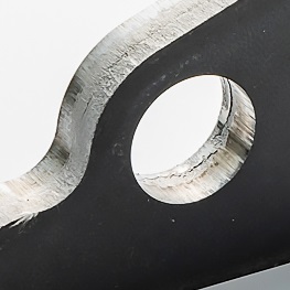
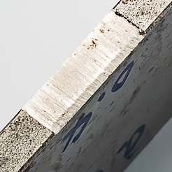
〈Photo: Side holes are also drilled〉
【Issues with Material Yield in Deep Drawing】
Deep drawing is a typical sheet metal forming process used to produce cylindrical or case-shaped components. However, manufacturing often faces issues such as:
・Uneven thickness during deep drawing
・Cracking at the bottom or shoulder areas
・Earing and wrinkling
・Large amounts of scrap after blanking
With rising material costs, scrap handling has become a critical factor affecting overall product competitiveness.
【What Is Deep Drawing】
〈Plastic forming that transforms sheet metal into 3D shapes〉
Deep drawing forms cup- or cylindrical shapes by pressing sheet metal with a punch and die.
Stable deep drawing requires:
・Proper blank diameter design based on material properties
・Optimization of blank holder force
・Appropriate punch and die radii (R)
・Controlled lubrication conditions
Kawamura Kikai Co., Ltd. operates 50 press machines (10–500 t) and supports processes such as deep drawing, bending, blanking, and trimming, backed by over 70 years of metal press expertise.
【Multi-Stage Scrap Utilization】
〈Maximizing material usage〉
The company reuses scrap from the first product to produce additional parts, sometimes up to four stages. Through optimized blank design and process planning, materials are used more efficiently while maintaining forming quality.
【Thickness Control Technology】
〈Preventing localized thinning〉
To prevent localized thinning, the company applies:
・Radius (R) design to control material flow
・Multi-stage forming to distribute forming loads
・Fine adjustment of blank holder force
・Process planning based on prior deformation history
These methods help achieve uniform thickness and stable product quality.
【Applications】
Typical deep-drawn components include:
・Motor cases
・Cover parts
・Cylindrical brackets
・Various housing components
Uniform thickness improves both appearance and durability, while scrap reuse enhances material yield and cost efficiency.
【Key Considerations When Evaluating Deep Drawing】
〈From single-part optimization to system optimization〉
Important factors include:
・Balance between required depth and sheet thickness
・Material strength and ductility
・Connection with downstream processes
・Potential improvement in material yield
If multiple parts can be produced from the same material sheet, blank layout and dimensional relationships should be optimized from the early design stage.
Because the company designs and manufactures dies in-house, it can quickly implement shape modifications and process improvements during prototyping, enabling efficient transition to mass production.
【Summary】
Deep drawing requires precise material flow control. By combining uniform thickness forming with multi-stage scrap utilization, manufacturers can improve material efficiency while maintaining product quality.
【Contact Information】
Kawamura Kikai Co., Ltd.
Head Office: 2-4 Shimizu-cho, Itabashi-ku, Tokyo 【Composite Division】
Hanazono Factory: 10 Kitane, Fukaya-shi, Saitama 【Metal Press Division】
Website: https://www.kawamura-kikai.co.jp
Inquiry / Quotation: https://www.kawamura-kikai.co.jp/contact/
Consultations are available from the early design stage for deep drawing and material reuse–oriented process design. Sharing drawings or current issues will help identify the optimal manufacturing approach.
【Do You Assume Fracture Surfaces Are Unavoidable?】
In press blanking, fracture surfaces are often considered inevitable.
However, in precision components such as gears, fitting holes, and sliding parts, they can cause accuracy loss, wear, noise, and looseness.
Although fine blanking offers high-quality shear surfaces, its cost and limitations can be restrictive.
An effective alternative is precision shearing using general-purpose presses.
【What Is Precision Shearing】
〈Maximizing shear surface by suppressing fracture〉
Precision shearing applies high constraint pressure to reduce fracture and increase the smooth shear area, ideally achieving full-shear through the thickness.
Benefits:
・Improved surface finish
・Stable perpendicularity and accuracy
・Reduced burrs
・Enhanced fitting performance
It also enables reduction or elimination of secondary machining processes.
【Achieving Full Shear with General Press Machines】
〈Precision without dedicated equipment〉
Full-shear can be achieved with general press machines by optimizing die design and process conditions.
Kawamura Kikai Co., Ltd. leverages extensive press expertise and 50 machines (10–500 t) to develop precision shearing on standard presses.
At the prototype stage, full-shear has been achieved by optimizing:
・Clearance based on material and thickness
・Die geometry for material flow
・Die rigidity
・Pressing conditions
【Manufacturing System and Capabilities】
〈Flexibility through in-house die production〉
With 70+ years of experience, the company handles die design, manufacturing, and maintenance in-house, enabling fast improvement cycles for:
・Prototype optimization
・Mass production durability verification
・Wear-based die modification
Additional processes such as spot welding, riveting, and assembly are also supported, allowing optimization at the unit level.
【Typical Applications】
Precision shearing with general presses is effective for:
・Gear and tooth-profile components
・High-precision hole brackets
・Thin sheet parts requiring strength and fit
・Mass-production parts targeting machining reduction
Stable shear surfaces reduce burrs and variation, improving assembly stability and productivity.
【Key Considerations When Evaluating Precision Shearing】
When considering precision shearing, the key question is not whether specialized equipment exists, but how well processing conditions can be designed.
Important factors include:
・Current shear surface ratio
・Impact of fracture surfaces on part functionality
・Potential to reduce secondary machining
・Dimensional stability in mass production
Even at the prototype stage, feasibility studies based on drawings or existing parts can help identify optimal processes.
【Summary】
Precision shearing is not only about higher accuracy, but also about improving overall manufacturing efficiency and quality stability.
With optimized die design and processing conditions, it is possible to approach full-shear results even with general press machines.
If shear surface quality or machining reduction is a concern, reviewing the forming process may provide a practical solution.
【Contact Information】
Kawamura Kikai Co., Ltd.
Head Office: 2-4 Shimizu-cho, Itabashi-ku, Tokyo 【Composite Division】
Hanazono Factory: 10 Kitane, Fukaya-shi, Saitama 【Metal Press Division】
Website: https://www.kawamura-kikai.co.jp
Inquiry / Quotation: https://www.kawamura-kikai.co.jp/contact/
Consultations regarding precision shearing and full-shear processing using general press machines are available from the early planning stage. Sharing drawings or current challenges will help identify the most suitable processing method.
We are developing technologies aimed at prototyping and mass production of composites using thermoplastic resins. For thermoplastic resin-impregnated carbon fiber (CFRTP), we support materials up to PEEK resin. Using heat & cool, both hot press and cold press with a preheating heater are possible. Mold size is supported up to 1200×1500mm, and product size is supported up to 800×600mm (approx.). Prototyping and mass production are possible. Equipment is located in Itabashi-ku, Tokyo, and facility tours are available.
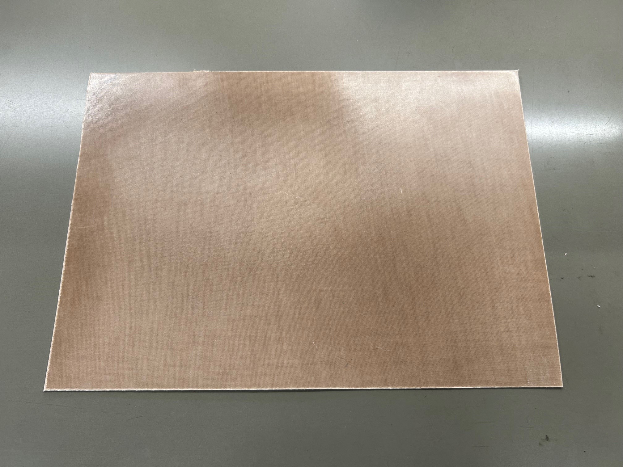
Carbon fiber–based composites are the mainstream in composite molding. However, Kawamura Kikai Co., Ltd. has developed its own intermediate materials (prepregs) using natural fibers.
The material shown in the image is made from naturally derived resin (hemicellulose) and natural fiber (cacao husk). Naturally, this prepreg can also be used for composite molding applications.
In addition, we are developing bio-based and natural fiber materials such as bio-resin PA11 (derived from castor oil) manufactured by Arkema, as well as natural fibers including FLAX, HEMP, and coconut fiber.
We welcome inquiries from those seeking natural fiber–based composite materials.
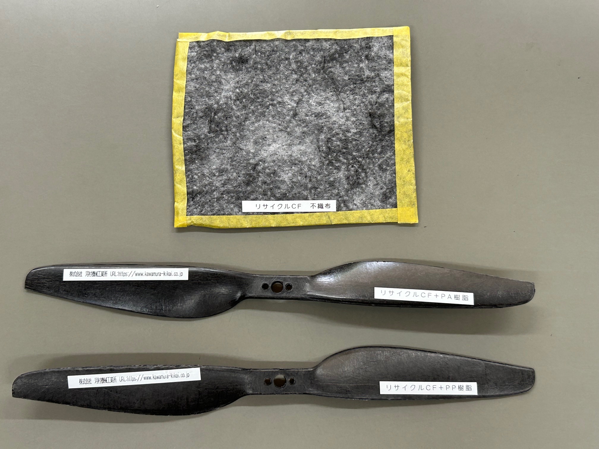
Carbon fiber materials widely used in the market are often CFRP (Carbon Fiber Reinforced Plastic) impregnated with thermosetting resin. Aircraft structures, golf club shafts, and fishing rods are typical examples made from CFRP. Because CFRP uses thermosetting resin, recycling is difficult. Research institutions and companies have been developing methods to recycle only the carbon fibers by heating the material to decompose the resin component.
Using this recycled carbon fiber, felt-like (nonwoven) materials have been developed. Our company is advancing technological development for molding processes using these materials. The upper photo shows the recycled carbon fiber nonwoven material, and the lower photo shows a molded product made from this material.
We actively propose the commercialization of products utilizing recycled carbon fiber.
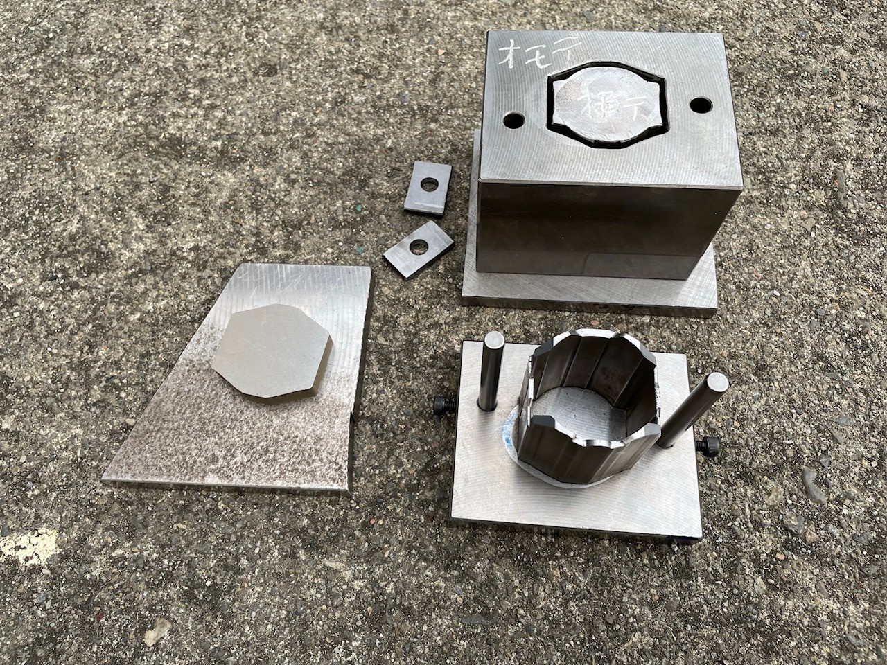
In composite molding, multiple layers such as prepregs or preforms are often stacked together. Depending on the material volume and thickness, materials may overflow or protrude from the mold. As a result, pressure distribution becomes uneven, and the intended shape may not be achieved.
An effective solution to these issues is the use of a preforming die in the molding process.
【What Is a Preforming Die?】
A preforming die is an intermediate mold used to compress and roughly shape materials before final molding.
When stacked materials cannot properly fit into the final mold in one step, they are first compressed in a preforming die to create an intermediate product (a preform shape). This intermediate product is then placed into the final mold for pressing.
By stabilizing material flow in advance, the final product achieves:
Improved shape accuracy
More uniform pressure distribution
Cleaner surface finishes
【Advantages of Using a Preforming Die】
Although it may seem like adding an extra step, introducing a preforming die offers significant benefits:
Reduced material loss
Prevention of uneven material distribution or overflow
Improved yield rate
More stable product quality
Optimized laminate structure
Enhanced strength and dimensional accuracy
In many cases, even with an additional process, overall production efficiency and cost performance improve.
【Application to Chopped Fiber Molding】
Preforming dies are also effective when molding chopped fiber materials.
Chopped fiber materials consist of short fibers randomly mixed together and are suitable for complex shapes and small components. However, directly loading chopped fibers into the final mold can lead to:
Fiber distribution unevenness
Complicated and time-consuming manual work
Instead, chopped fibers can first be compressed and shaped into a billet (intermediate product) using a preforming die. The billet is then placed into the final mold for molding.
Compared to manually placing chopped material into fine areas with tools such as tweezers, using intermediate billets offers:
Faster processing
Higher repeatability
Improved product uniformity
Especially in mass production, combining billet preforming with final molding helps establish a stable production cycle and significantly enhances productivity.
【Cost Benefits】
Manufacturing a preforming die or billet mold requires initial investment in time and cost. However, over the long term, the reduction in material waste and process inefficiencies often results in greater cost savings.
This is particularly valuable when working with expensive composite materials. Minimizing waste has substantial economic benefits. In addition, improved product consistency reduces inspection and rework costs.
Overall, this approach enables:
Lower total production costs
Higher product quality
Greater process stability
【Summary】
Introducing a preforming die is not merely an additional process step—it is a strategic improvement that enhances molding quality, material yield, and productivity.
It is especially effective for:
Complex-shaped components
Chopped fiber molding
Applications where material flow and filling are challenging
Although it involves initial setup costs, it is increasingly recognized as a technology that balances long-term cost efficiency with high-quality manufacturing.
For operations seeking greater molding stability and improved quality, incorporating a preforming die into the process design is a highly effective option.
【Contact Information】
Kawamura Kikai Co., Ltd.
Head Office: 2-4 Shimizu-cho, Itabashi-ku, Tokyo 【Composite Division】
Hanazono Factory: 10 Kitane, Fukaya-shi, Saitama 【Metal Press Division】
Website: https://www.kawamura-kikai.co.jp
Inquiry / Quotation: https://www.kawamura-kikai.co.jp/contact/
Please mention that you saw us on “Emidas” when making your inquiry.
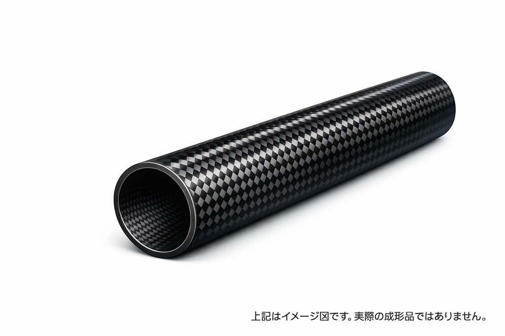
Pipe manufacturing using CFRTP (Carbon Fiber Reinforced Thermoplastics) is gaining attention as a method that combines lightweight properties, high strength, and excellent mass productivity.
The method introduced here utilizes a braided CFRTP preform, combining press molding and air injection to efficiently form pipe shapes. Compared with conventional CFRP pipe manufacturing, this process significantly reduces production time and offers cost advantages.
【Overview of CFRTP Pipe Molding】
Because CFRTP uses a thermoplastic resin matrix, it can be repeatedly softened by heating and hardened by cooling. This characteristic enables fast processing with a press machine.
In this method, a braided CFRTP preform is used. The process begins by wrapping the braided preform around a tube-shaped base material.
Thanks to the flexibility and fiber orientation freedom unique to braided structures:
Strength can be adjusted by controlling winding angles
Uniform pipe structures can be formed
Required rigidity can be secured efficiently
【Molding Process Flow】
The process consists of four main steps:
1. Wrapping the Braided CFRTP Preform
The flexible braided preform is carefully wrapped around a base tube.
By adjusting the fiber orientation during wrapping, the rigidity and strength direction of the pipe can be optimized.
2. Press Molding in a Heated Die
The wrapped assembly is placed in a mold shaped to the desired pipe geometry and hot-pressed.
As the thermoplastic resin softens:
Fibers conform tightly to the mold surface
The outer shape is precisely defined
3. Air Injection
After press forming, air is injected into the interior of the pipe.
This internal pressure:
Stabilizes the inner diameter
Ensures uniform wall thickness
Improves overall rigidity and dimensional accuracy
4. Cooling and Solidification
While still set in the mold, the component is cooled.
As the thermoplastic resin solidifies:
Final strength is established
Shape accuracy is fixed
A lightweight, high-rigidity CFRTP pipe is completed
【Comparison with Conventional Methods】
Carbon fiber pipes are commonly produced using CFRP (Carbon Fiber Reinforced Thermosetting Plastics).
In conventional manufacturing:
Prepreg is wrapped around a mandrel
The assembly is cured in an autoclave
While this method produces high-quality pipes, it requires long heating and curing times, limiting productivity.
In contrast, CFRTP pipe molding:
Utilizes thermoplastic resin properties
Enables short cycle times
Allows rapid press-based processing
Supports continuous production for standardized sizes
Higher productivity directly contributes to cost reduction.
【Application Potential of CFRTP Pipes】
CFRTP pipes offer:
Lightweight construction
High impact resistance
Fast manufacturing speed
Potential applications include:
Mechanical components
Sporting goods
Transportation equipment requiring weight reduction
The braided preform structure allows more flexible fiber orientation design than traditional CFRP pipes, enabling performance customization according to specific application needs.
【Summary】
By combining braided CFRTP preforms, press molding, and air injection, this manufacturing method enables the production of lightweight and high-strength pipes in a short time.
Compared with conventional autoclave molding:
Production efficiency is significantly improved
Manufacturing costs can be reduced
Rapid prototyping and small-lot production are feasible
Although size limitations exist, this process is highly effective for components within a practical dimensional range.
If you are exploring lightweight, high-strength, and cost-efficient pipe solutions, CFRTP pipe molding presents a strong alternative worth considering.
【Contact Information】
Kawamura Kikai Co., Ltd.
Head Office: 2-4 Shimizu-cho, Itabashi-ku, Tokyo 【Composite Division】
Hanazono Factory: 10 Kitane, Fukaya-shi, Saitama 【Metal Press Division】
Website: https://www.kawamura-kikai.co.jp
Inquiry / Quotation: https://www.kawamura-kikai.co.jp/contact/
Please mention that you saw us on “Emidas” when making your inquiry.
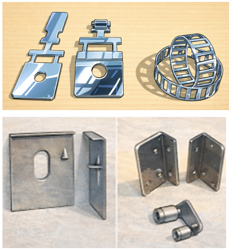
In metal press processing, what truly matters is precision, stable supply, and ease of consultation.
Not only drawing, bending, and blanking, but also whether you can entrust dies, welding, assembly, and surface treatment to one company makes a significant difference in both workload and quality.
“I'm not sure which supplier to choose.”
“Managing multiple processes separately is complicated.”
To reduce these concerns, one-stop production support is increasingly being chosen.
Common Challenges
Managing multiple vendors for different processes is complicated
Uncertainty about selecting the right processing method, leading to cost and quality concerns
Prototypes perform well, but quality becomes unstable in mass production
These issues often arise when processing and post-processing are outsourced
separately.
What Is Metal Press Processing?
Metal press processing is a manufacturing method in which sheet metal is shaped using dies and pressure.
By combining drawing, bending, and blanking operations, a wide range of component shapes can be produced.
It is highly suitable for mass production, enabling the stable supply of uniform-quality parts.
Advantages of One-Stop Production
In-house die design and manufacturing through press processing
Selection of optimal methods such as single-stage or transfer press according to product requirements
Integrated support for welding, caulking, assembly, and surface treatment
By entrusting even the post-processing steps, you can significantly reduce the workload related to ordering, coordination, and quality control.
Industries Served
Automotive and truck components
Railway-related parts
Decorative hardware and design components
Housing equipment and building materials
We support components requiring high precision and repeatability.
Benefits of Consolidating Your Orders
A single point of contact
Reduced variation in quality
Prevention of rework and delivery delays
Reliable transition from prototyping to mass production
Start with a Consultation
Even if your drawings are not yet finalized, that’s no problem.
We can assist from the stage of reviewing processing methods and organizing
production steps.
From prototype to mass production, we will work with you to determine the most
practical and efficient approach.
【Contact Information】
Kawamura Kikai Co., Ltd.
Head Office: 2-4 Shimizu-cho, Itabashi-ku, Tokyo 【Composite Division】
Hanazono Factory: 10 Kitane, Fukaya-shi, Saitama 【Metal Press Division】
Website: https://www.kawamura-kikai.co.jp
Inquiry / Quotation: https://www.kawamura-kikai.co.jp/contact/
Please mention that you saw us on “Emidas” when making your inquiry.
We also operate a Composite Division.
Composite Division URL: https://www.kawamura-kikai.co.jp/composite/

We have a track record in the design and manufacturing of automotive parts.
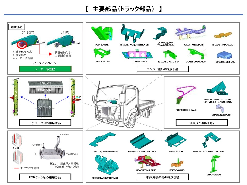
We have experience in the design and manufacturing of truck parts.


