Language: 日本語 | English
Language: 日本語 | English
【Crankshaft Quenching Machine】
When quenching pins and journals of crankshaft simultaneously, miniaturizing transformers (disk transformer) or quenching towards the same direction as turning pins allows formation of a quenching layer along a pin diameter.
“Power reduction method,” top and bottom uniformed quenching technique by reducing the output on the pin top for R-quenching, can minimize the possibility of distortion.
The above quenching technique can be in-line and for such case, we will gladly design to match the customer’s request.
Please feel free to contact us.

[Idler Hardening Machine]
At Fuji Denshi, we manufacture and sell induction hardening machines
and also do job heat treatment.
This photo shows the hardening of an idler.
With our original technology, we achieve high strength and precision
hardening even for difficult large parts.
Our one-shot circumference hardening ensures high productivity for
large parts such as gears, idlers, and rollers.
Traditional hardening methods cannot prevent uneven hardening.
Also, when using ring coils, hardening must be done separately
on both sides of the idler.
With our methods, our original semi-open coil repeats heats with
intermittent breaks, gradually heating the rotating workpiece and
preventing unevenness.
This method also decreases total consumed power and greatly
reduces cycle time, achieving high productivity.
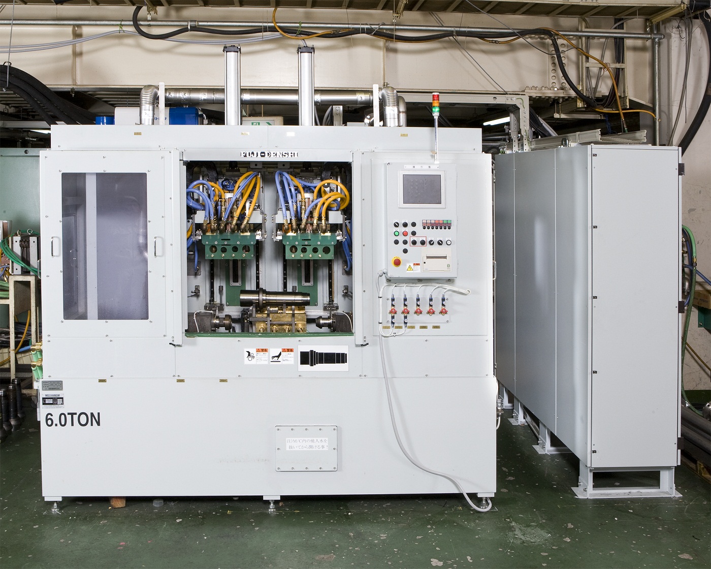
The photo shows the hardening station of an automobile power train CVJ
(constant velocity joint) outer surface induction hardening
and reheating machine.
The outer stem and cup grooves are hardened at one station
using the same converter.
Reheating is done at a separate station with a separate converter.
※At Fuji Denshi, we refer to tempering as reheating to differentiate
from furnace methods.
The process on this machine is
・loading
↓
・stem heating
↓
・stem quenching, cup heating
↓
・cup quenching
↓
・reheating
↓
・after quenching
↓
・unloading
By combining the hardening stations while keeping the reheating
station separate, we achieved a remarkably short cycle time of
under 30 seconds per workpiece while maintaining high quality.
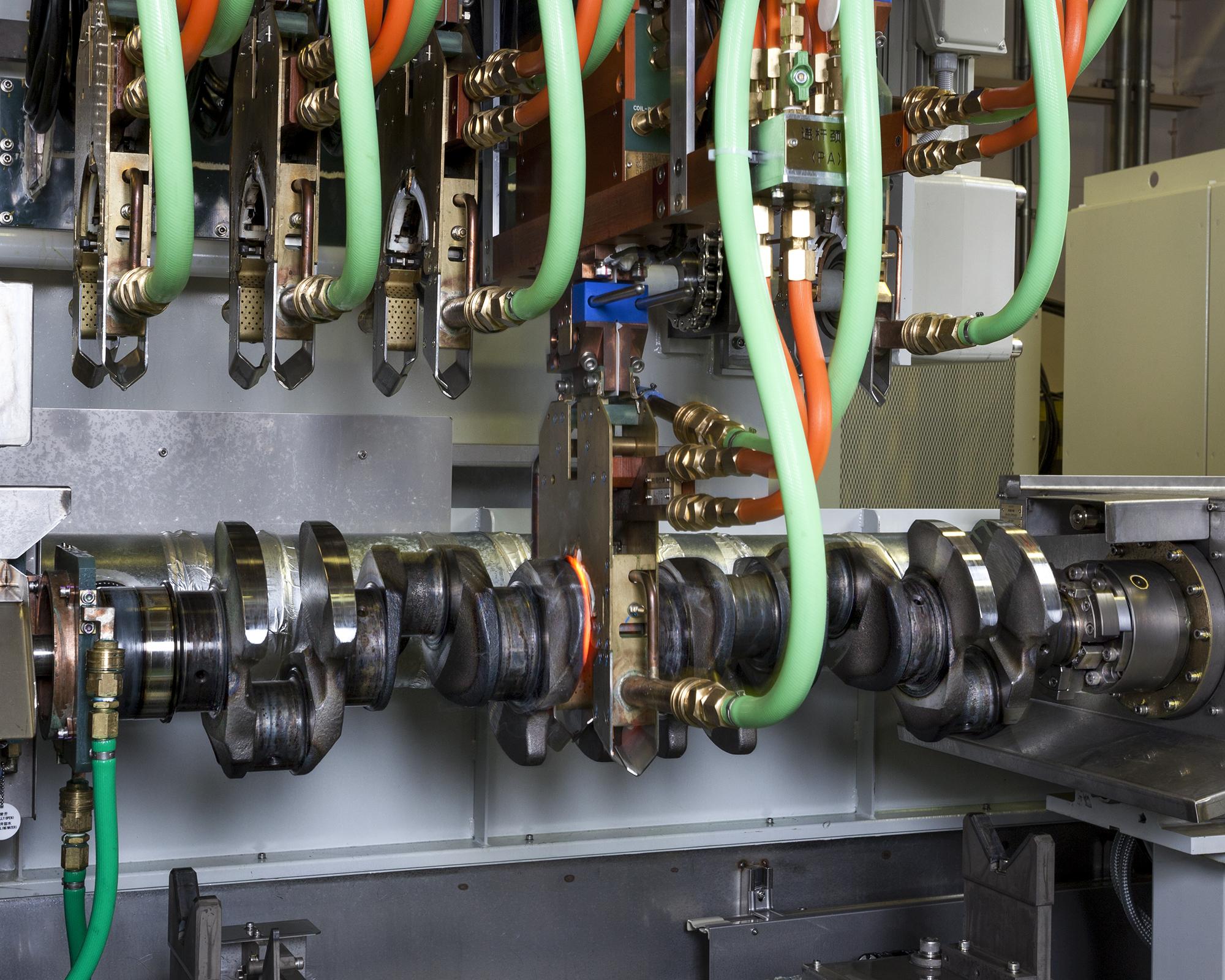
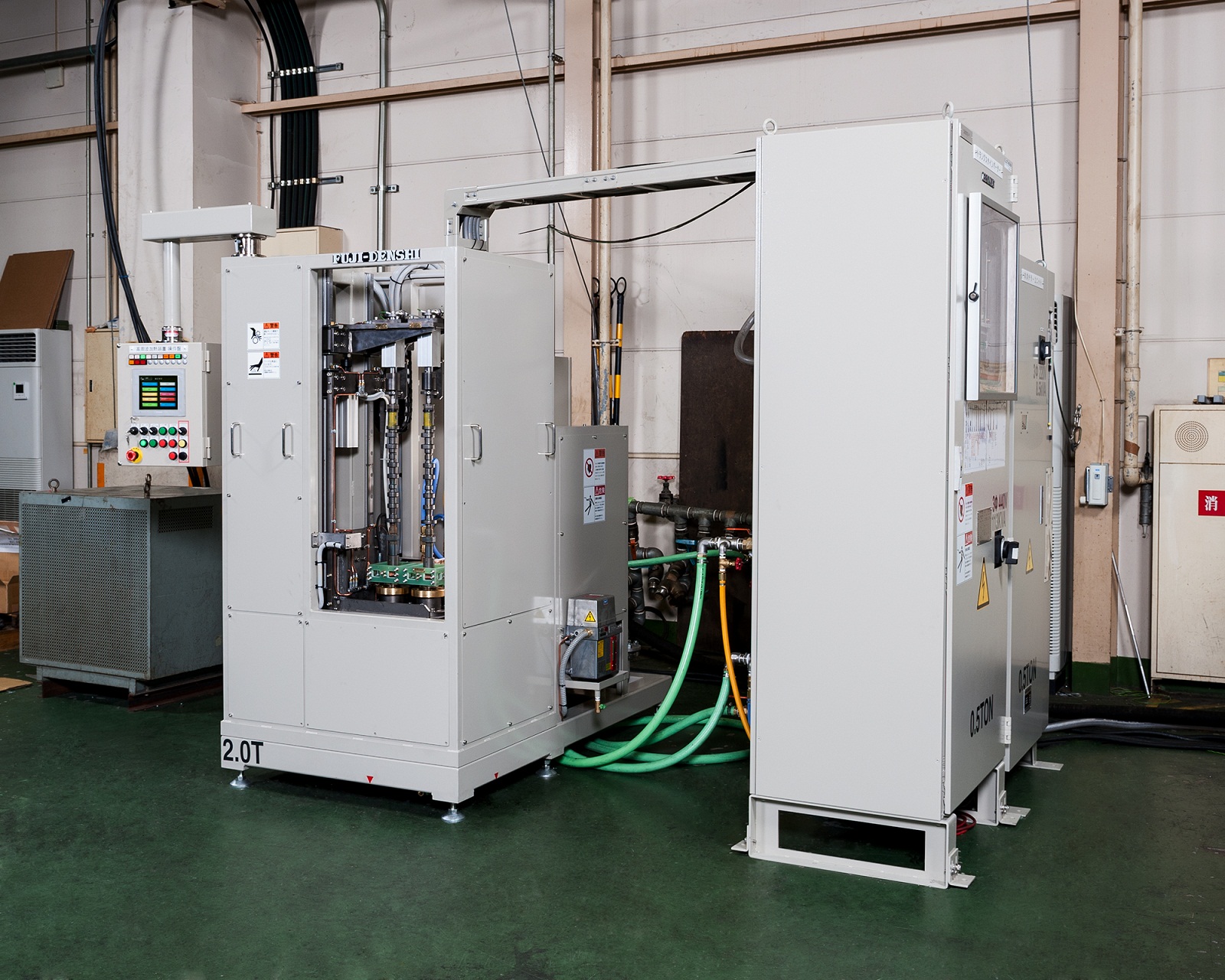
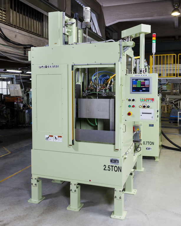
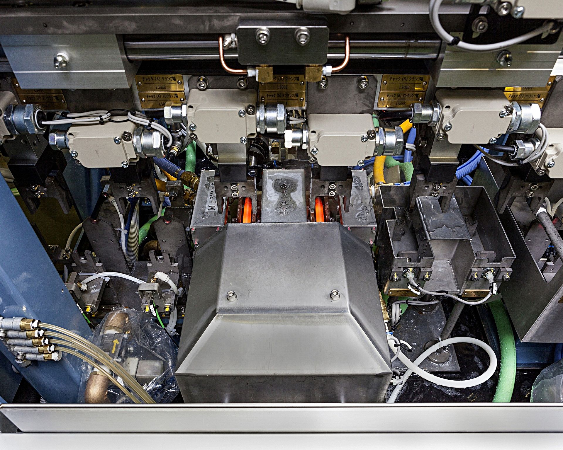
The photo shows an automobile V6 engine crankshaft induction hardening
and reheating machine.
This machine is installed in-line at an engine plant.
It receives the workpiece from the previous process, performs hardening
automatically, and sends the workpiece to the next process.
The workpiece is loaded from the port on the right.
First the pins are induction hardened at the right and center stations,
followed by the journals at the left station.
Finally the work is unloaded from the port of the left.
This machine performs flat hardening, which in general is a simpler process,
but to achieve the specified short cycle time of under 50 seconds,
the machine was designed with two converters and three hardening stations for high productivity.
~Crankshaft Induction Hardening Machine Flat Hardening
High Productivity Automobile Prats IH Heat Treat~
The photo shows the double axle vertical scan hardening station of
an induction hardening machine for automobile transmission parts.
The workpiece, a clutch release fork (clutch lever), is hardened
at the two tips by semi-open coils.
After heating, the workpiece is carried down and quenched outside of the coil.
The green plate seen behind the coil is the quenching jacket,
which sprays quenching water from diagonally above the workpiece.
In addition to one-shot hardening as seen in the photo, the coils and jigs
can be exchanged for vertical scan hardening as well.
~Transmission Parts Induction Hardening Machine ③ Automobile Parts
IH Heat Treat~
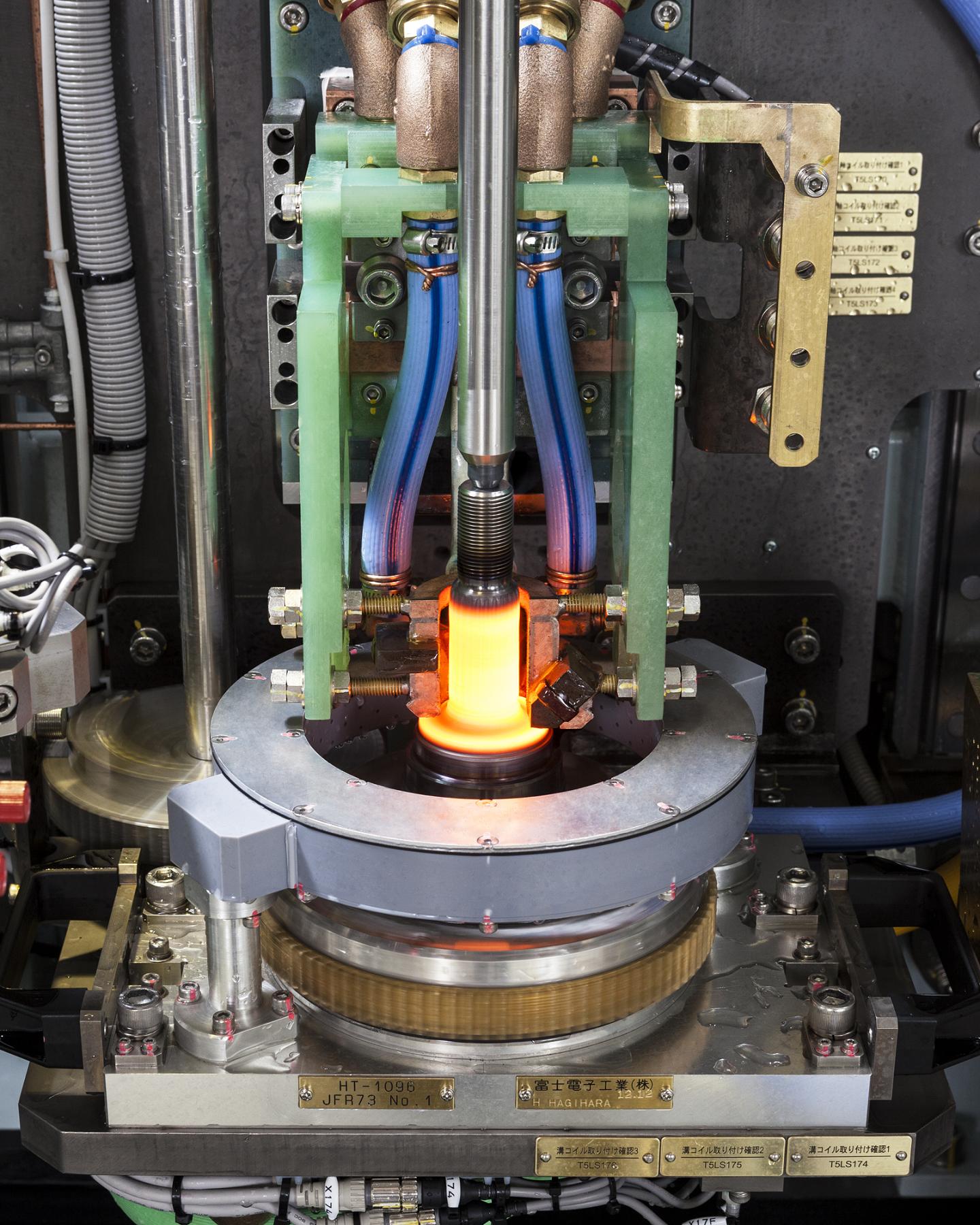
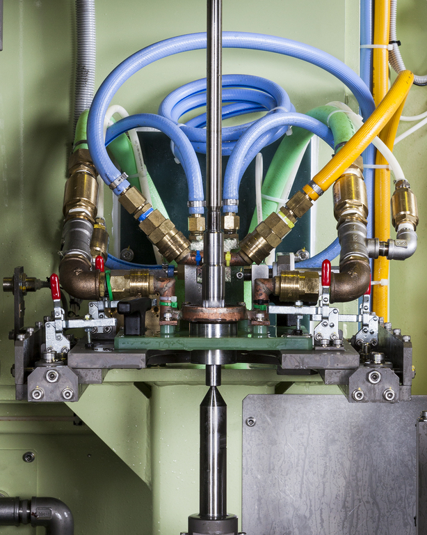
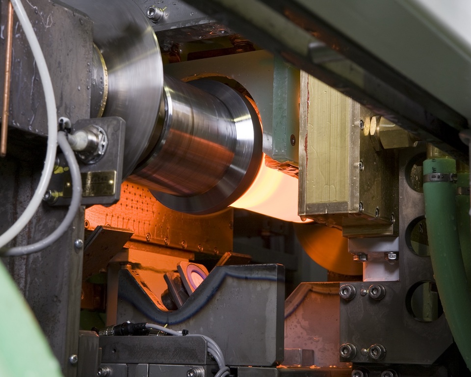
The photo shows the hardening station of a motorcyle engine assembly
crankshaft induction hardening and reheating machine.
※At Fuji Denshi, we refer to tempering as reheating to differentiate from
furnace methods.
In the photo, two sections of the shaft are induction heated.
The spray quenching jacket is combined with the coil unit for a rapid
heating-quenching process.
To perform hardening and reheating with the same machine, the converter is
designed to switch between two frequencies.
Even with two heating-quenching cycles, the cycle time is kept under 1 minuteper workpiece.
~Assembly Crankshaft Induction Hardening Machine Reheating Machine
Double Axle Parts IH Heat Treat~
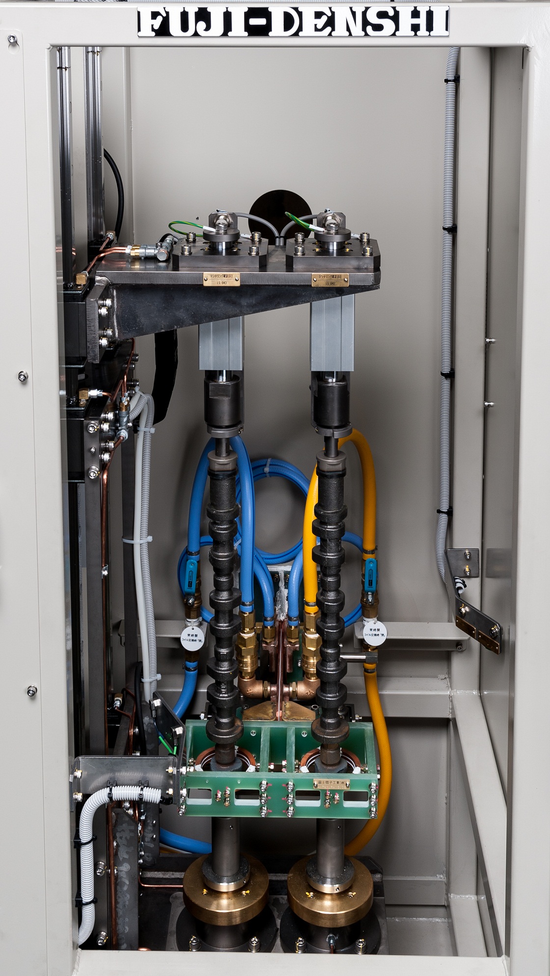
The photo shows the hardening station of a vertical scan induction hardening machine
for shafts used in motors, generators, and alternators.
This automatic machine can induction hardening various motor shafts from
automobile alternators to vessel generators.
Our vertical scan hardening machine can be designed to move not only the workpiece, but also the coil and power transformer unit.
With this design, we decreased the size of the hardening station and
the entire machine as well as made loading and unloading easier.
As a result, this machine performs high quality hardening while
decreasing operation time.
[Job Heat Treat]
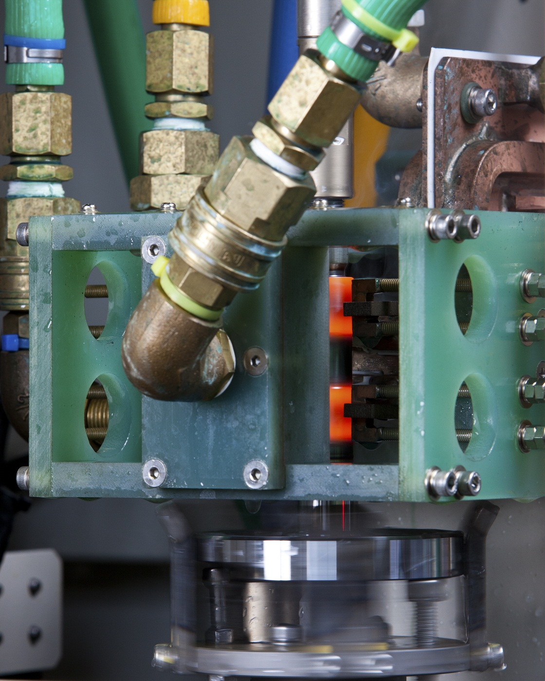
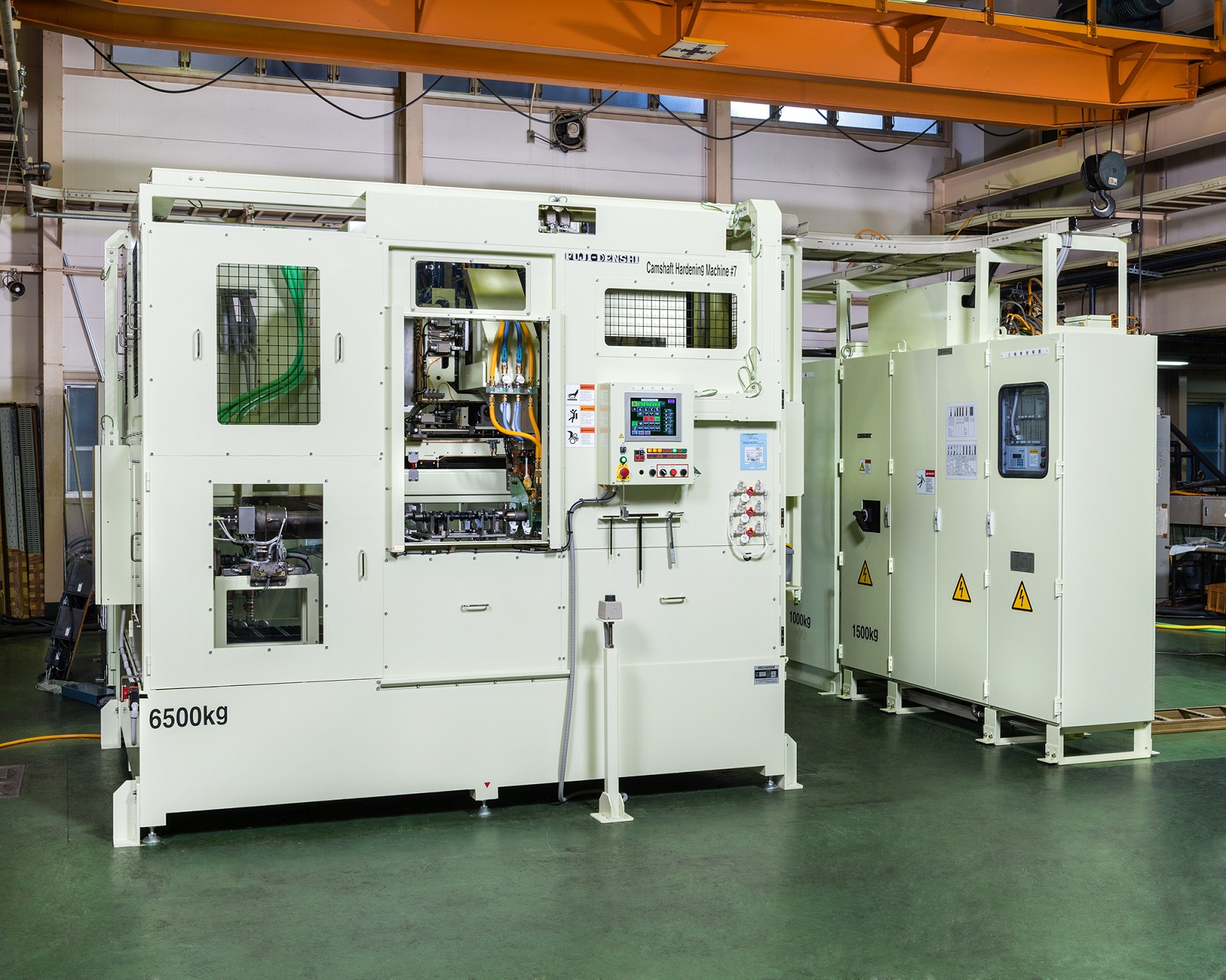
The photo shows a camshaft induction hardening and reheating machine.
This machine hardens two camshafts simultaneously with manual loading
and automatic unloading.
Fuji Denshi's camshaft hardening machine uses our patented eccentric
tracking mechanism.
The coil follows the rotating cam nose to achieve even heating.
Our original coil design smoothly heats the cam and prevents temperature
difference over the cam surface.
The quenching jacket is designed to control the water volume for even
quenching of each cam.
Using these technologies, cracking and uneven residual stress are reduced,
minimizing cracking during grinding while also achieving an even
casing and low runout.
The high-speed design also contributes to shorter cycle time.
[Custom-made Machines]
The photo shows the heating station of an automobile engine
camshaft pump cam induction heating machine.
To austemper the ductile iron pump cam, the cam is heated to over 1,100°C
and quenched in the adjacent salt bath.
To effectively heat the triangular shaped target area,
the rotating workpiece is heated with low frequency using a multi-turn coil
until a certain depth is reached.
After thorough calibration, we were able to meet the severe
heating specifications of minimum 1,100°C and range ±20°C
for two differently shaped target areas.
The photo shows the hardening station of a truck powertrain axle shaft induction hardening machine.
The multi-diamater axle shaft surface is evenly heated using our
semi-open line coil.
In the photo, the quenching jacket is raised, but during the actual process,
the jacket rotates 90° forward and moves down to the workpiece
for spray quenching.
The horizontally oriented workpiece is held by the centering unit,
then rotated by the straightening roller from below during heating
and quenching.
This method achieves hardening with low run out for thick, long,
and multi-diameter shafts.

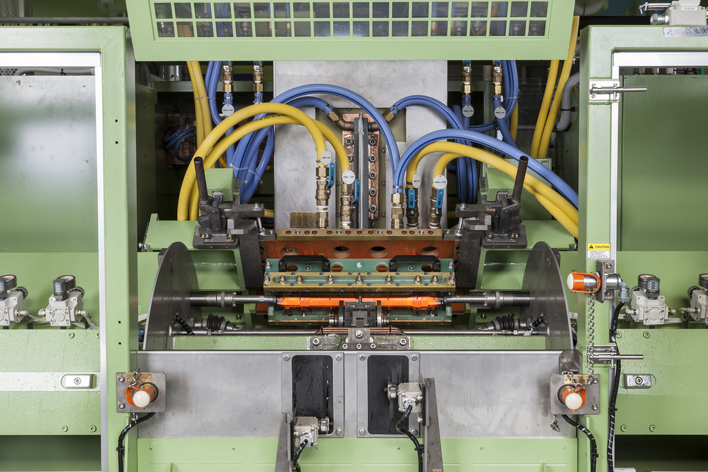
The photo shows the hardening station of an automobile power train CVJ
(constant velocity joint) outer surface induction hardening and
reheating machine.
The hardened ares are the outer stem and cup grooves.
As seen in the photo, as the workpiece rotates the stem is induction heated.
The brown heating coil around the workpiece is our original semi-open line coil.
The benefits of our line coil include:
- deep hardening depth in the curved corners of multi-diameter shafts
- continuous case pattern over the shaft, curved, and flange sections
to prevent soft areas and achieve durability
- simple loading and unloading for short cycle time
With these features, this machine achieves a cycle time of
under 30 seconds per workpiece.
[Custom-made Machines]
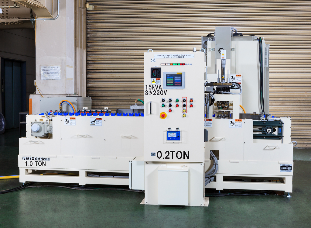
The photo shows an automobile steering upper shaft
induction annealing machine.
After forming with a press, the desired sections of the hardened workpiece
are induction heated for annealing.
One converter is used to anneal two workpieces simultaneously,
allowing for a compact machine design.
※The size of the manual loading/unloading machine without conveyor
is seen on the right.
We continue to develop methods to make our machines
as compact as possible.

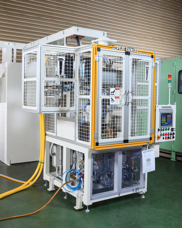
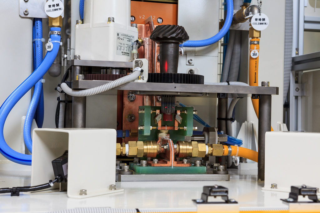
The photo shows an automobile powertrain driveshaft (half shaft)
induction hardening machine.
In the front is the hardening machine and above it are two gantry loaders
for loading and unloading.
In the back left is the incoming panel and converter.
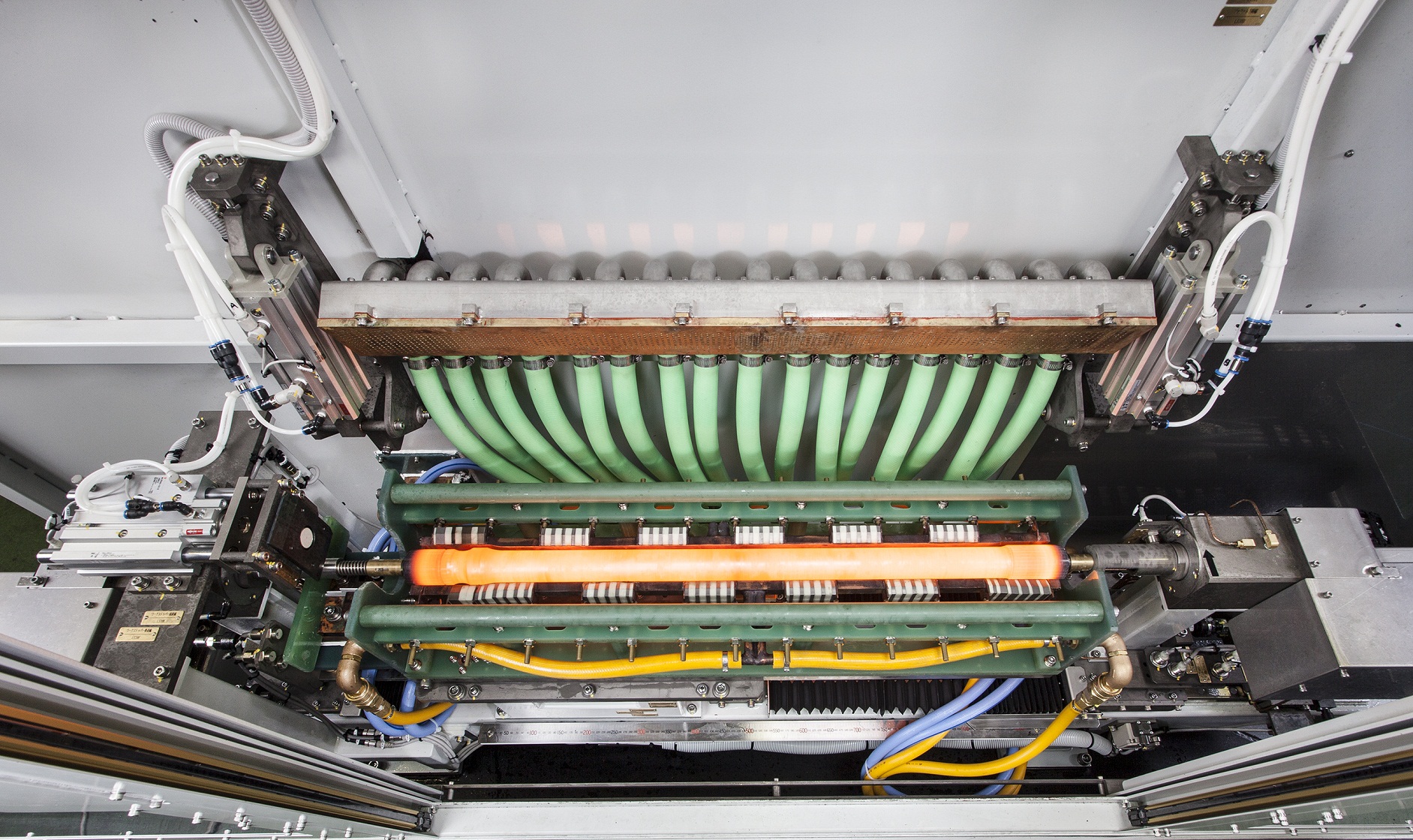
The workpiece in the center of the hardening machine is glowing red
during heating.
To the left of the hardening machine, a workpiece is waiting on a jig.
The same type of jig is also to the right of the machine, not seen in the photo.
The workpiece is picked up by the robotic arm, turned horizontally 90˚,
carried over the machine by the gantry loader and loaded
into the heating station.
After heating and quenching, the other gantry loader unloads the workpiece
and carries it to the next process.
This machine was specially designed for our semi-open line coil
and achieves a remarkably short cycle time of 20 seconds per workpiece.

Double Axle Vertical Scan Induction Hardening Machine 2 Units
These machines were installed in a customer's overseas job heat treatment plant.
The inner surface of the 400mm length workpiece is induction hardened.
As the inner surface diameter ranges between 50~120mm,
the converter is designed to switch between two frequencies.
We made special adjustments to the machine's motor positioning
to meet our customer's request to minimize the height of the machine.
The height of the loading/unloading unit was also designed
to match the height of the operator.
[Custom-made Machines]
This is an induction annealing machine for automobile pinion shafts.
After the entire surface is hardened by carburizing, only the tip section
is annealed by induction.
Annealing does not require rapid quenching like hardening,
so the machine design is very compact.
As seen in the photo, the work is automatically loaded from the left
and carried to the annealing station.
After annealing, the workpiece is automatically unloaded.
We continue to develop machines with high productivity
using the simplest possible design.
The workpiece in the center of the hardening machine is glowing red
during heating.
The green box with handles is the coil unit, featuring a semi-open coil unit
positioned over the workpiece.
For muilt-diameter shafts, our machines are designed so the case depth is
sufficient even in the cruved corners of the shaft surface.
The workpiece shown is the thinnest and lightest of its kind in the industry,
and our machine is designed to make precision hardening possible
using our dip spray quench method and straightening roller for low runout.
~Driveshaft Induction Hardening Machine② Automobile Parts
IH Heat Treat~

This photo shows the heating station of our automobile transafer shaft
and helical shaft induction annealing machine.
After the entire surface is hardened by carburizing,
only a section is annealed by induction.
The photo shows the workpiece after annealing.
The flange shaped section of the middle workpiece appears blue
after being heated.
While we at Fuji Denshi maintain induction hardening as one of
our specialties, we also specialize in annealing of parts hardened
by carburizing, machining, and welding.
The photo shows the heating station of an automobile engine
camshaft pump cam induction heating machine.
To austemper the ductile iron pump cam, the cam is heated
to over 1,100℃ and quenched in the adjacent salt bath.
Pictured to the right are the transistorized converter and control panel,
and to the middle and left are the hardening machine and matching panel.
Loading/unloading is done by robot, and 2 workpieces are heated
at the same time. As a result, 2 workpieces are treated in under 1 minute.
For austempering, the heated workpiece is quickly unloaded
by the robot and transported to the salt bath.
This machine was designed for extreme compactness,
as the quenching water circuits in typical hardening were not necessary.
~Camshaft Pump Cam Induction Heating Austemper Machine ①
Automobile Parts IH Heat Treat~

This photo shows the hardening station of our autmobile engine
crankshaft flange hardening machine.
The workpiece is loaded/unloaded from above by robot.
After the workpiece is set on the rotating jig, the coil unit moves forward
to the heating position, and heats the workpiece as it rotates around its axis.
The photo shows the crankshaft flange being heated by the induction coil,
which is behind the green disc-shaped spray jacket.
After heating, the coil unit moves slightly back to the quenching position,
and quenching water is sprayed onto the workpiece from the spray jackets.

The photo shows the hardening station of our all-purpose hardening
machine for automobile parts.
This machine has two hardening stations, enabling it to harden
two different types of workpieces if equipped with different coils and jigs.
Treatable parts include:
・Shift fork
・Clutch release fork
・Lever striking
・Bracket
and other such parts for automobile transmission, which have difficult shapes
including curves and teeth.
In the photo, the teethed section of a bracket is being induction hardening
at the right-hand station.
To the left of the heated workpiece is the gold-colored spray quench jacket,
which rapidly quenches the workpiece after heating.
At the left-hand station, a lever striking is sitting on the jig ready for heating.
The photo shows our truck powertrain axle shaft induction hardening
and reheating machine.
※At Fuji Denshi, we refer to tempering as reheating to differentiate
from furnace methods.
In the photo, the rotating shaft is induction hardened using our
semi-open line coil.
The green device above the workpiece is the heating coil and the gold devices
in front of and behing the workpiece are the quenching jackets.
To quickly quench the entire shaft, two large volume spray jackets are placed
on both sides of the workpiece.
Even considering the large size of the workpiece, this machine achieves
a cycle time of under 2 minutes for hardening and reheating one workpiece.

The photo shows the hardening station of our automobile camshaft
induction hardening and reheating machine.
In the photo, two noses of two camshafts are being induction heated.
After heating, the coils move laterally and at the same time
the quenching jackets moves from the left over the cams
to rapidly quench them.
Our camshaft hardening machine uses our patented eccentric tracking
mechanism, where the hardening coils follow each cam nose as the shaft
rotates to achieve even heating.
Our originally developed coils are also designed to prevent temperature
difference over the cam surface.
The quenching jackets are designed to even quench each cam without
using excess quenching water.
Using these technologies, we are able to reduce cracking during hardening
as well as cracking during grinding caused by uneven stress, while achieving
an even cashing and low runout.
~Camshaft Induction Hardening Reheat Automobile Parts IH Machine②~
The photo shows the heating station of an automobile engine camshaft
pump cam induction heating machine.
To austemper the ductile iron pump cam, the cam is heated to over 1,100℃
and quenched in the adjacent salt bath.
To effectively heat the triangular shaped target area,
the rotating workpiece is heated with low frequency using
a multi-turn coil until a certain depth is reached.
In the photo, the pump cam is heated to a depth close to the shaft axle.
After thorough calibration, we were able to meet the severe heating
specifications of minimum 1,100℃ and range ±20℃ for two differently
shaped target areas.
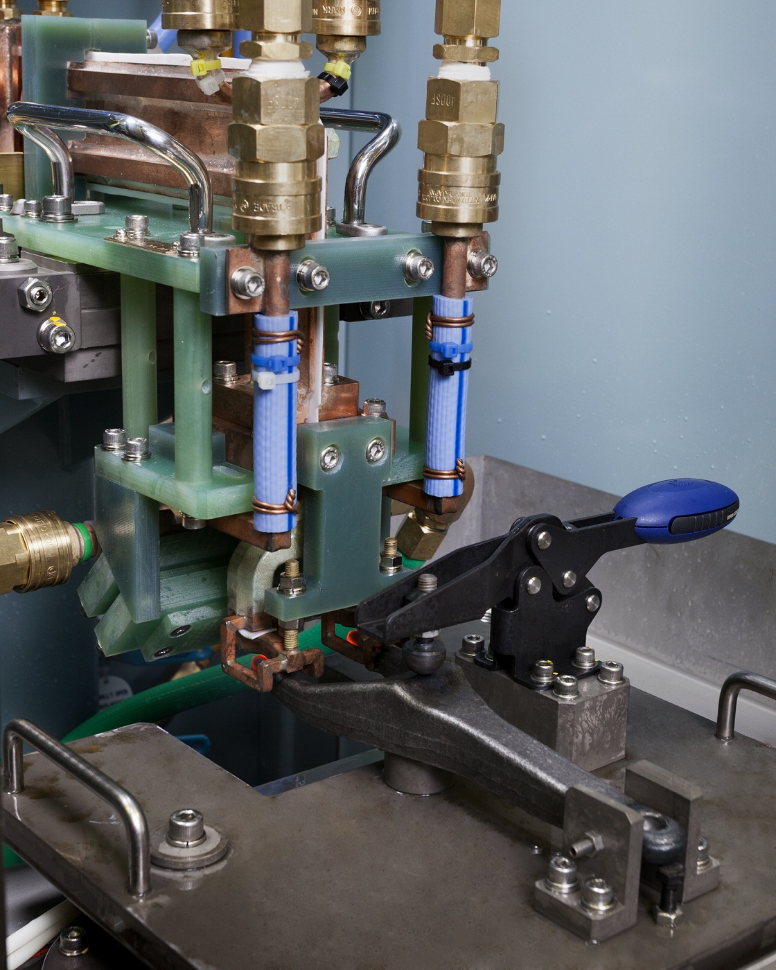
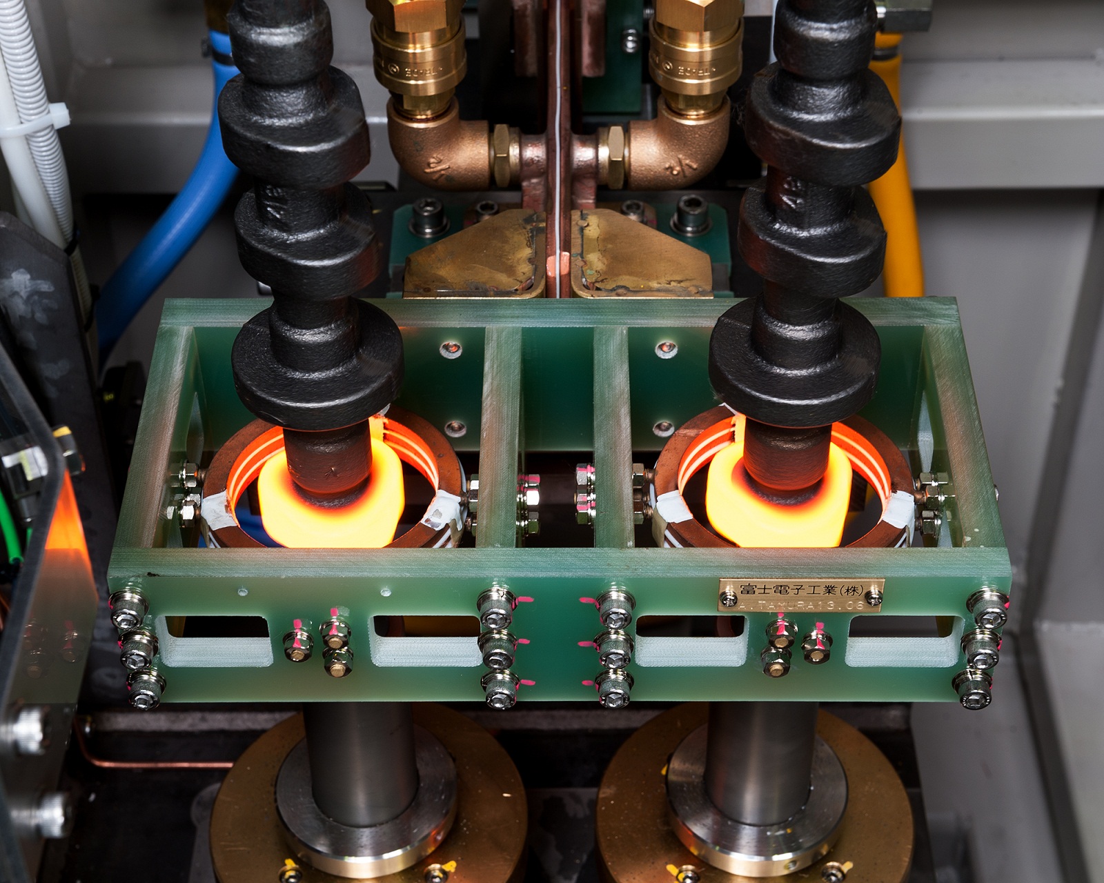
The photo shows the single rotating axis hardening station of
an induction hardening machine for automobile transmission parts.
The workpiece, a clutch release fork (clutch lever), is rotated
while heating the inner surface of the center hole.
Our original small spiral multi-turn coil to treat the extremely difficult
multi-diameter hole inner surface.
After heating, the workpiece is carried down out of the coil
and spray quenched by jackets on both sides.
The photo shows our vertical scan induction hardening machine for shafts
used in motors, generators, and alternators.
This machine can treat various shafts including for automboile alternators
and ship generators.
By setting parameters including output power, frequency, coil type,
workpiece size, feed speed, and quenching water flow,
our vertical scan hardening machine achieves high repeatability
As a result, runout is kept to a minimum for high quality hardening
and reduced operation time.

[Custom-made Machines]
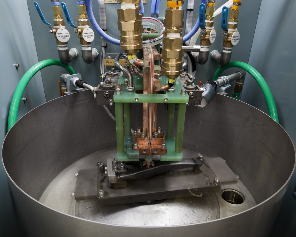
The photo shows the hardening station of our double axis
vertical scan induction hardening machine.
This machine can treat workpieces from inner diamater Φ50 to Φ120.
In the photo, one coil unit is simultaneously treating two workpieces.
Quenching water is sprayed from the hole in the receive jig seen
at the bottom for rapid quenching.
In this scan hardening machine, the heating coil and quenching jacket
are combined into one unit.
The photo shows the hardening station of our all-purpose hardening machine
for automobile parts.
This machine has two hardening stations, enabling it to harden
two different types of workpieces when equipped with different coils and jigs.
Treatable parts include:
・Shift fork
・Clutch release fork
・Lever striking
・Bracket
and other such parts for automobile transmission, which have difficult shapes
including curves and teeth.
To treat curved sections, a MOSFET transistorized converter
capable of outputing frequencies of 100~300kHz is used.

[Custom-made Machines]
At Fuji Denshi, we design and manufacture induction heating machines
to our customer's specifications.
The photo shows a truck powertrain axle shaft induction hardening machine.
The workpiece can be seen at the hardening station in the center of the photo.
This machine is able to treat shafts of various diameters and length.
This machine was designed for manual loading/unloading
due to the small lot size of truck axle shafts and the need to treat workpieces
of different specifications.
The green unit under the workpiece is the heating coil.
To minimize runout, this machine is equipped with a semi-open line coil
and a straightening roller.
The box-shaped unit in the back of the hardening station equipped with hoses
is the quenching jacket.
During hardening, the quenching jacket rotates forward 90˚ and the center door
closes to prevent quenching water from splashing.
~Axle Shaft Induction Hardening Machine① Automobile Parts
Induction Heat Treat~

[Heat Treat Plant]
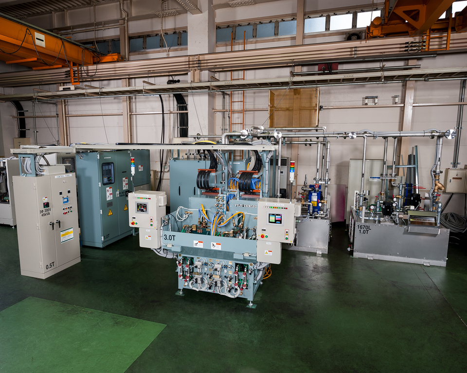
This machine can treat 3 different automobile transmission parts.
This system has 3 hardening machines sharing 1 converter.
From the left,
・single rotating axle hardening machine x 2
・double axle vertical scan hardening machine x 1
By changing the coils and jigs, all three machines can be retooled
to treat various workpieces.
The converter is also specified to switch between four frequencies
(80kHz, 100kHz, 200kHz, 300kHz) to treat various parts.
It also features an interlock circuit control to allow treatment of
various parts in succession.

[Custom-made Machines]
The photo shows an automobile steering upper shaft induction annealing machine.
After forming with a press, the desired sections of the hardened workpiece
are induction heated for annealing.
The workpiece is carried by the belt conveyer and positioned by the centering unit.
Then it is lifted into the machine, inserted into the coil, and heated.
The coil is specially designed to heat two workpieces simultaneously.

This photo shows the heating station of our automobile transafer shaft
and helical shaft induction annealing machine.
After the entire surface is hardened by carburizing, only a section
is annealed by induction.
The workpiece is automatically loaded into the annealing station,
and after annealing is automatically unloaded.
By synchronizing loading and unloading, a shorter cycle time was achieved.
This machine is one example of our simple yet highly productive
induction heating machines.

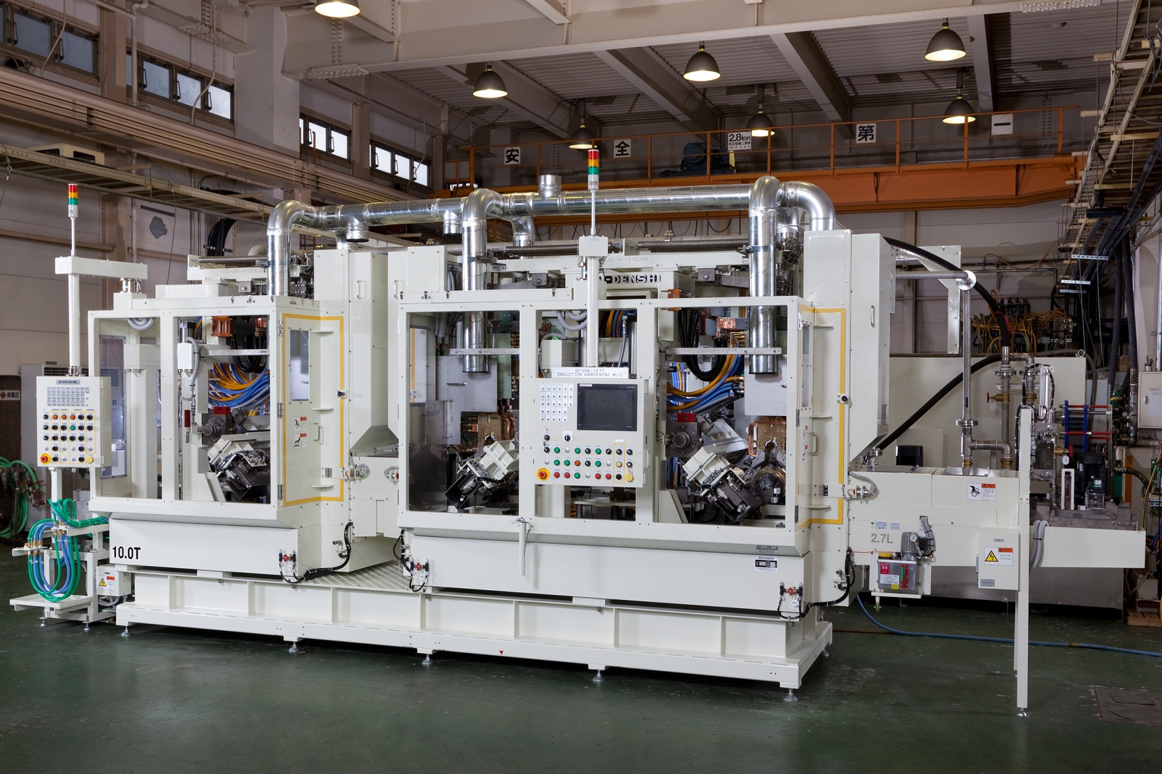
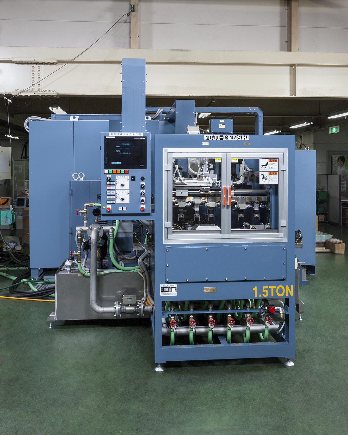
The photo shows an automobile engine crankshaft
induction hardening machine.
In the front right is the hardening machine,
to the left is the cooling water tank and quenching water tank,
in the center is the incoming panel,
and to the right is the transistorized converter.
The hardening machine has been designed to optimize compactness
and the overall layout was designed to meet our customer's specifications.
This machine is installed in an engine production line,
where it receives the workpiece from the previous process,
and automatically sends it to the next process after hardening.

The photo shows an automobile engine crankshaft induction
hardening machine.
This machine is designed for fillet hardening of pins and journals of
compact, lightweight crankshafts.
This machine is installed in an engine production line,
where it receives the workpiece from the previous process,
and automatically sends it to the next process after hardening.
The workpiece is loaded from the left, then the pins are hardened
at the left hand station.
The journals are then hardened at the righthand station,
before the workpiece is unloaded to the right.
This machine is specified for compactness and short cycle time
(under 60 sec/pc).
This was achieved by designing and manufacturing coils to control
the high power at the fillet corners using the Elotherm method.
☆ In the Elotherm method, semi-open coils track the rotating workpieces,
achieving low distortion and even casing.
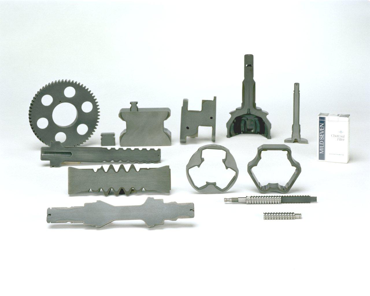
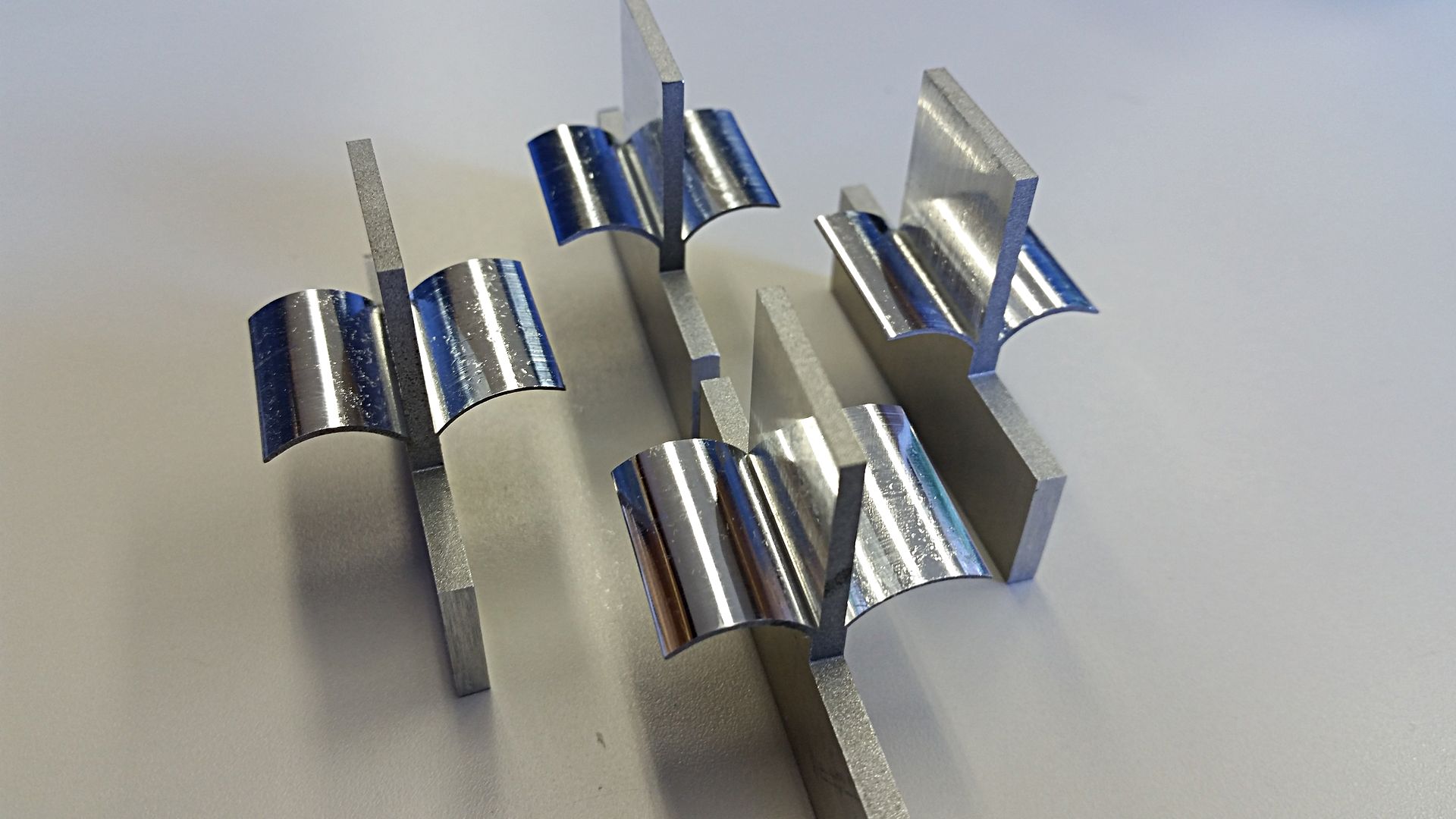
The photo shows cut samples of various machinery parts hardened
by our induction hardening machine.
The gray area of the cross section is the hardened casing.
As seen in comparison with the pictured cigarette box, the parts
are surprisingly small and the hardened areas are complexly shaped.
At Fuji Denshi, we apply our induction heating technology to meet
our customer's heat treat needs by supplying machines or providing
in-house job heat treat.
One of our specialties is heat treatment of large workpieces such as
construction machinery slewing bearing and machine tool beds and columns.
~Induction Hardening Cut Sample IH Heat Treat Automobile Parts
Production Machinery Parts~
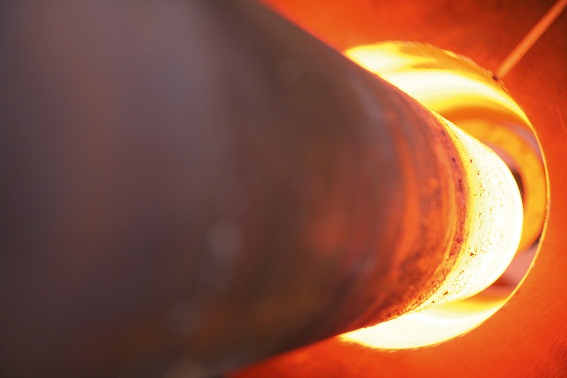
The photo shows a track powertrain axle pipe induction hardening
and reheating machine.
※At Fuji Denshi, we refer to tempering as reheating to differentiate
from furnace methods.
The pipe shaped workpiece is orientated horizontally in the hardening station.
This machine is able to treat pipes of various diameter and length
by retooling the machine.
This machine was designed for manual loading/unloading due to
the small lot size of truck axle shafts and the need to treat workpieces
of different specifications.
The green colored unit above the workpiece is the heating coil,
and the gold colored unit under the workpiece is the quenching jacket.
After the workpiece is loaded, the receive jig carries it down,
where it is held by the centering unit.
It is then lifted up, where model identification is done.
The workpiece is then carried under the appropriate coil for the workpiece model
and the coil is lowered onto the workpiece.
The workpiece is rotated while hardened.
Due to the large size of the workpiece, heating and quenching takes a
relatively longer time, but this hardening and reheating machine is able
to achieve a cycle time of 2 minutes per workpiece.
The photo shows the annealing station of our autmobile pinion shaft
induction annealing machine.
After the entire surface is hardened by carburizing, only the tip section
is annealed by induction. In particular, this machine anneals the workpiece
from the tip to the spline section.
Using our original semi-open coil, the workpiece is heated evenly along
its multi-diameter shape.
[Applications of Induction Heating]
● Pipe Rolling and Welding
Pipe seam and fin tube continuous welding, hoop and core welding,
pipe preheating
● Coating
Compact motor insulation resin coating, pipe antioxidizing layer coating
● Getters
Electrical tubes, neon tubes, display tubes, mercury lamps,
gas purge for flourescent lights, flash getters
● Semiconductors
Silicon monocrystal growth, epitaxial growth
● Cast Manufacturing
Heating of extrusion nozzle and forming dice, aluminum extrusion heating
● Heat Cycle Experiment
Metallic material heat cycle experiment, educational materials
● Annealing
Annealing of wires and stainless steel pipes, press pre-processing
including shaping and bending
Fuji Denshi's heating power units can be used for all of these applications
in addition to the hardening of steel parts.
Please contact us with any and all of your heating needs.
~Induction Induction Heating Applications Hardening~
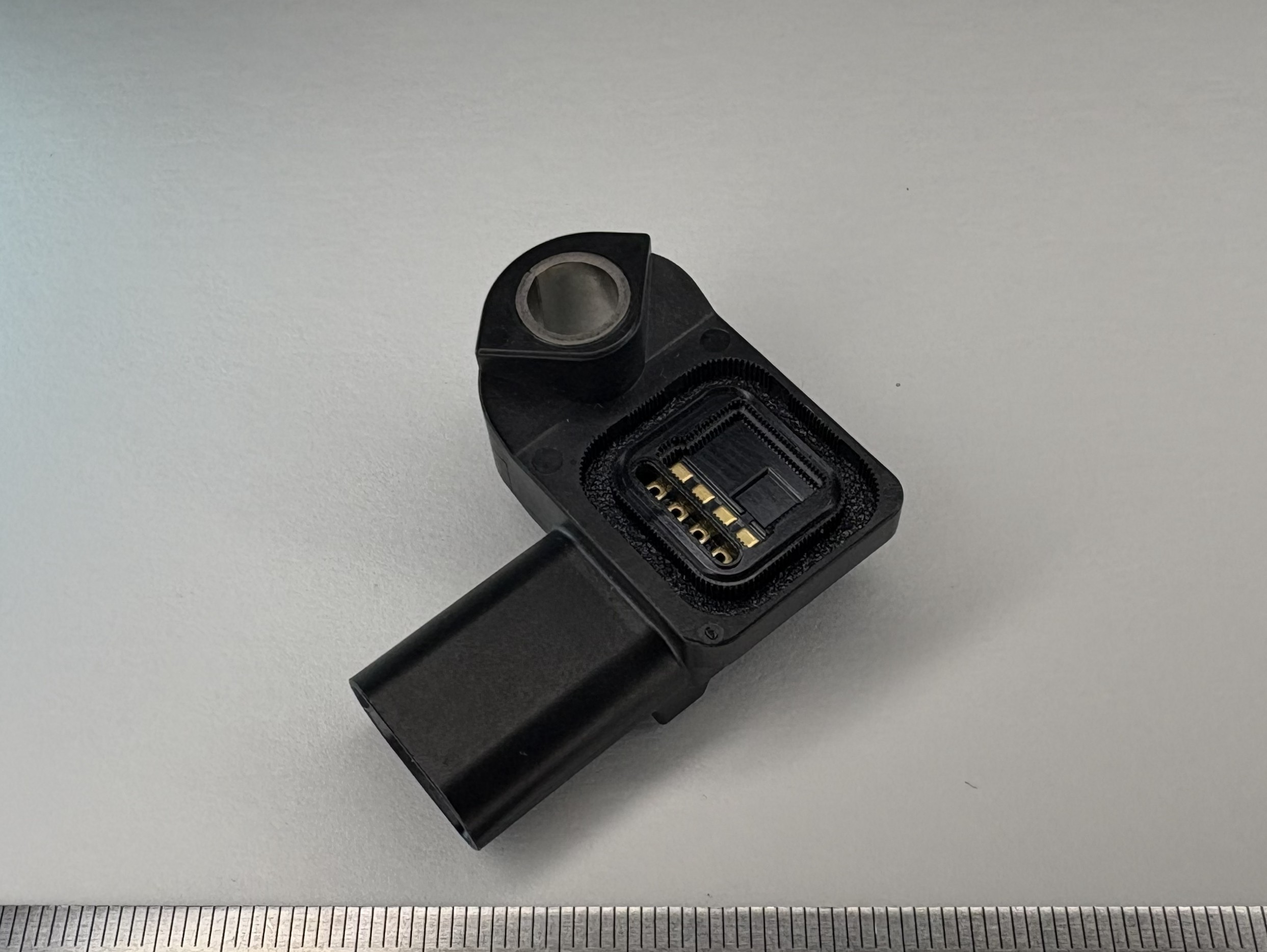
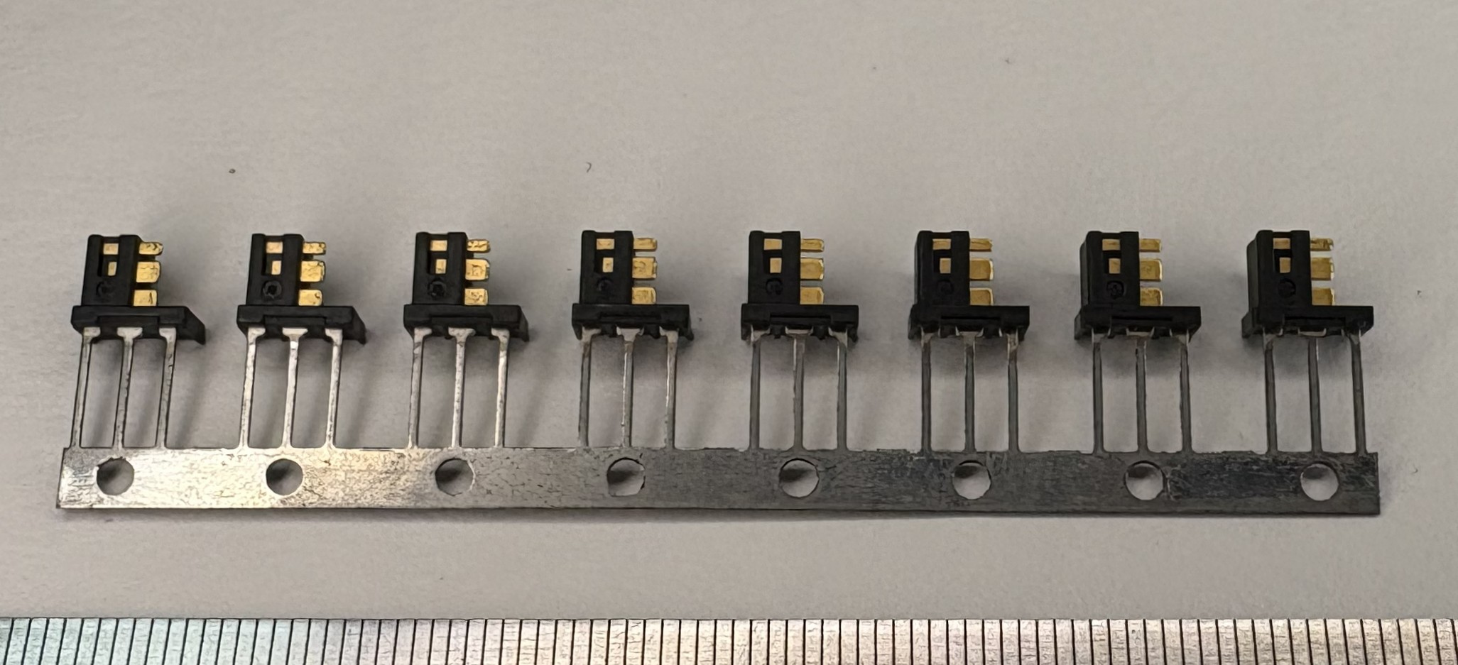
The photo shows an electronic device component designed for the automotive industry.
This insert-molded connector is manufactured using the following materials:
Resin: PBT
Terminals: Phosphor bronze
Leveraging our expertise in the design and manufacture of press dies and engineering plastic molds, we offer fully integrated, in-house production—from terminal press processing to insert molding—within a single facility.
IATF 16949 Certified
For stable, high-volume production of automotive components, trust your requirements to us.
“Technology, Perfected.”
Shinshu Yoshino Electric Co., Ltd.
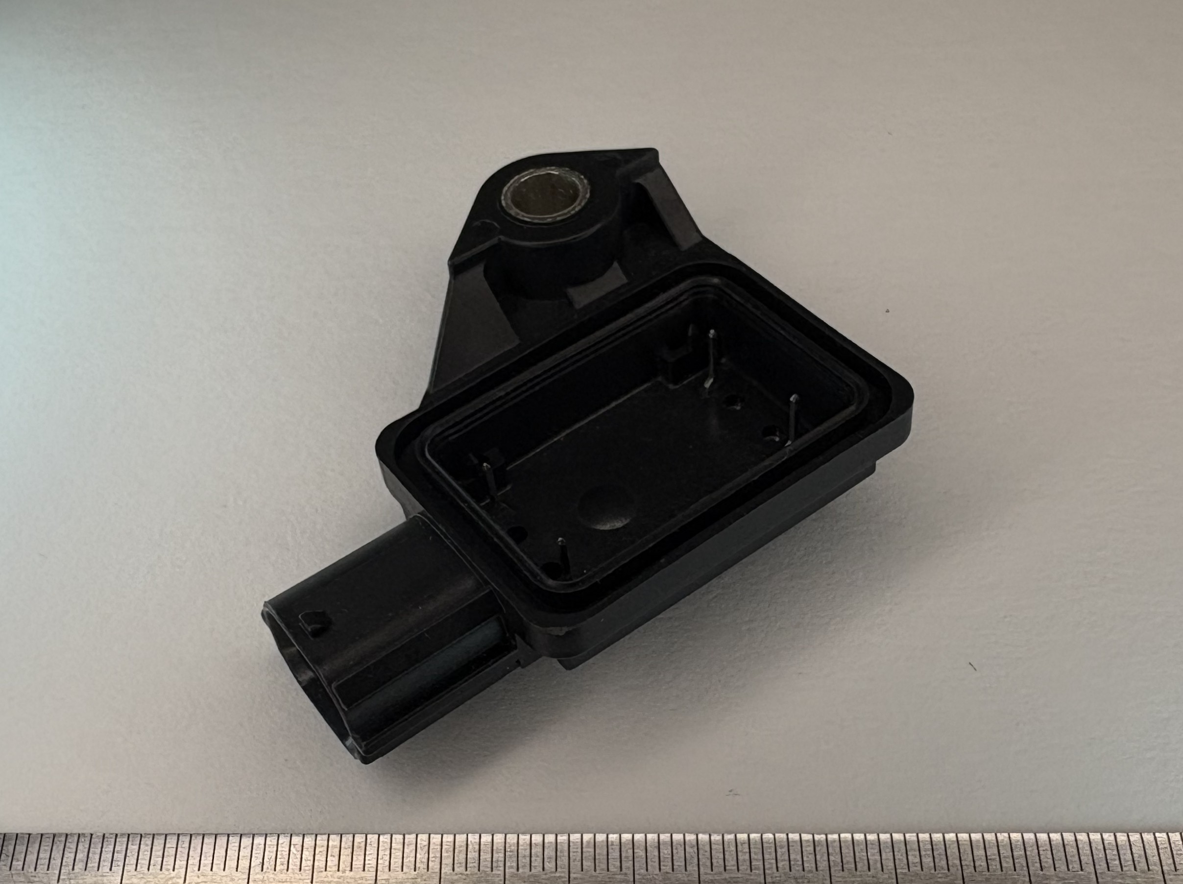
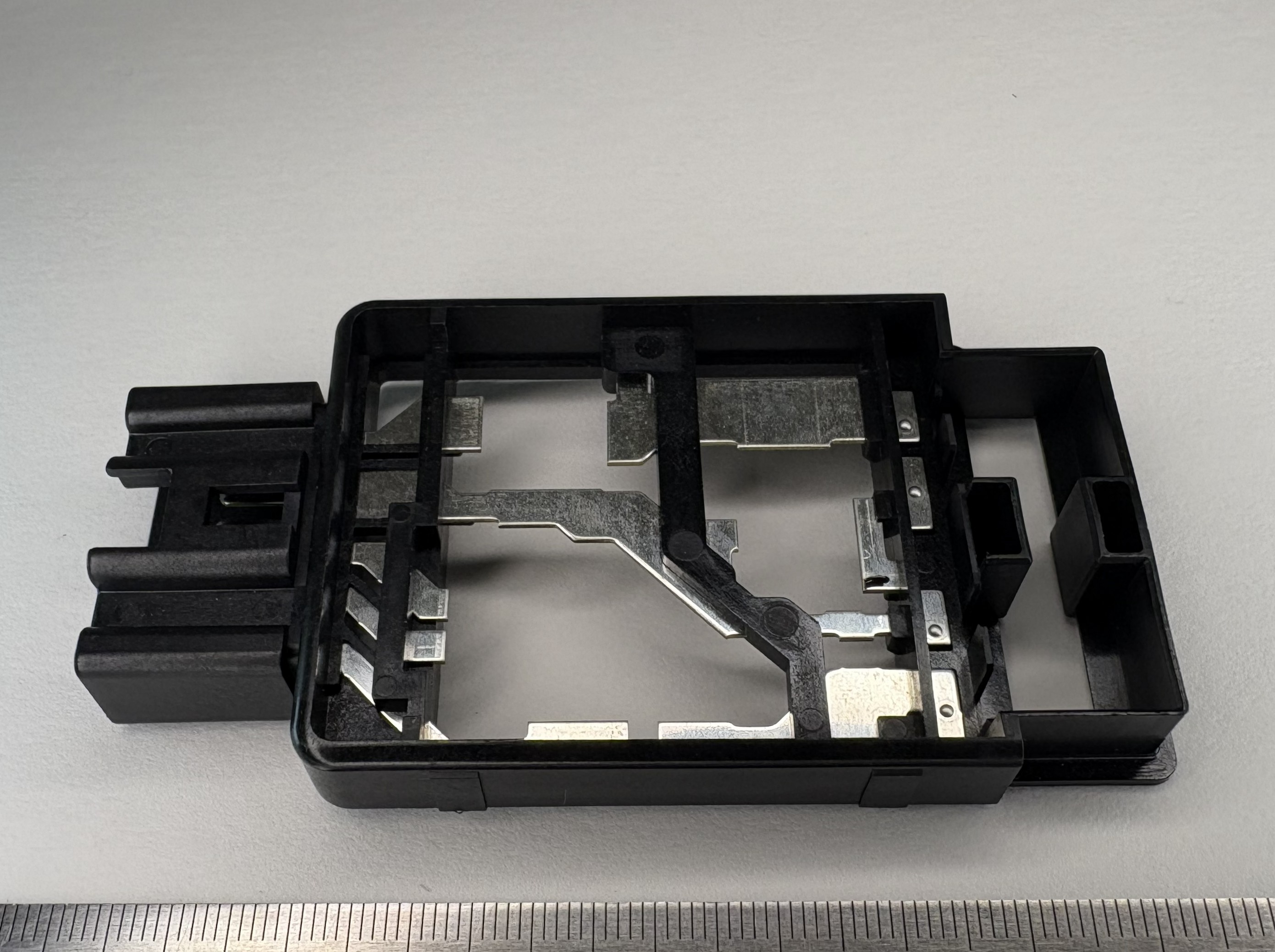
The photo shows an electronic device component developed for the automotive industry.
This insert-molded connector is manufactured using the following materials:
Resin: PBT
Terminals: Phosphor bronze
Pipe: Fe (steel)
Based on our expertise in the design and manufacture of press dies and engineering plastic molds, we provide fully integrated, in-house production—from terminal press processing to insert molding—within a single facility.
IATF 16949 Certified
For stable, high-volume production of automotive components, trust your requirements to us.
“Technology, Perfected.”
Shinshu Yoshino Electric Co., Ltd.
The photo shows an electronic device component designed for the automotive industry.
This insert-molded connector is manufactured using the following materials:
Resin: PPS
Terminals: Phosphor bronze
Pipe: Fe (steel)
Based on our expertise in the design and manufacture of press dies and engineering plastic molds, we provide fully integrated, in-house production—from terminal press processing to insert molding—within a single facility.
IATF 16949 Certified
For stable, high-volume production of automotive components, rely on our proven insert molding capabilities.
“Technology, Perfected.”
Shinshu Yoshino Electric Co., Ltd.
The photo shows an electronic device component for the automotive industry.
After insert molding, a secondary press operation is performed to achieve the final shape.
Materials
Resin: PPS
Terminals: Phosphor bronze
Leveraging our expertise in the design and manufacture of press dies and engineering plastic molds, we provide fully integrated, in-house production—from terminal press processing and insert molding to secondary press operations—all within a single facility.
IATF 16949 Certified
For stable, high-volume production of automotive components, trust your requirements to us.
“Technology, Perfected.”
Shinshu Yoshino Electric Co., Ltd.
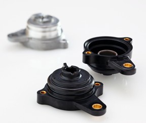
The photo shows a transmission component developed for the automotive industry.
Originally manufactured as a machined aluminum part, this component has been redesigned through a resin conversion VA (Value Analysis) proposal, achieving both weight reduction and cost optimization.
Materials
Resin: PPS
Insert screws: Brass
Pipe: Fe (steel)
Based on our expertise in the design and manufacture of press dies and engineering plastic molds, we provide fully integrated, in-house production—from terminal press processing to insert molding—within a single facility.
IATF 16949 Certified
For stable, high-volume production of automotive components and effective metal-to-resin conversion solutions, trust your requirements to us.
“Technology, Perfected.”
Shinshu Yoshino Electric Co., Ltd.
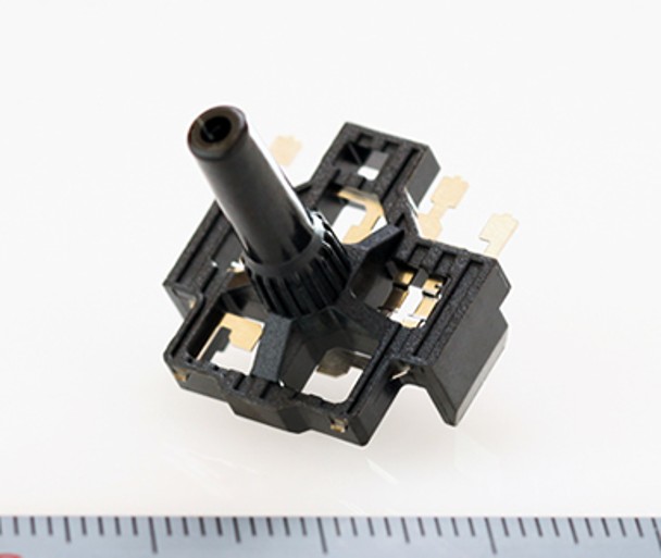
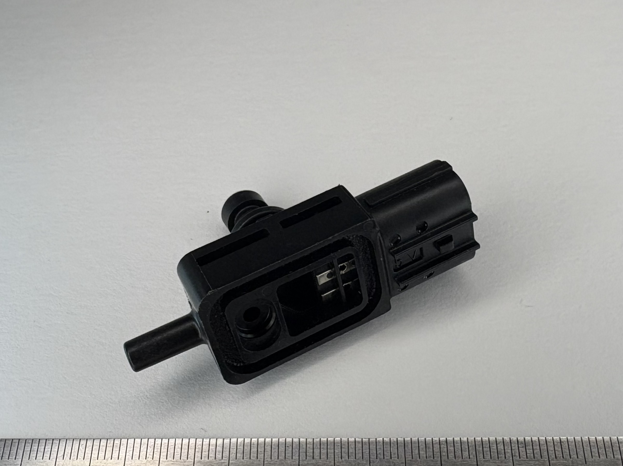
The photo shows an electronic device component for automotive applications,
used in fuel system assemblies.
The component is manufactured using hoop forming technology, with the following material configuration:
Resin: PPS (Polyphenylene Sulfide)
Terminals: Phosphor bronze
Based on our capabilities in design and manufacturing of metal stamping dies and engineering plastic molds, we provide a fully integrated production process within a single facility, covering everything from terminal stamping to insert molding.
IATF 16949 certified
For stable, high-quality mass production of automotive components, please rely on Shinshu Yoshino Denki.
“Technology, Perfected.”
Shinshu Yoshino Electric Co., Ltd.
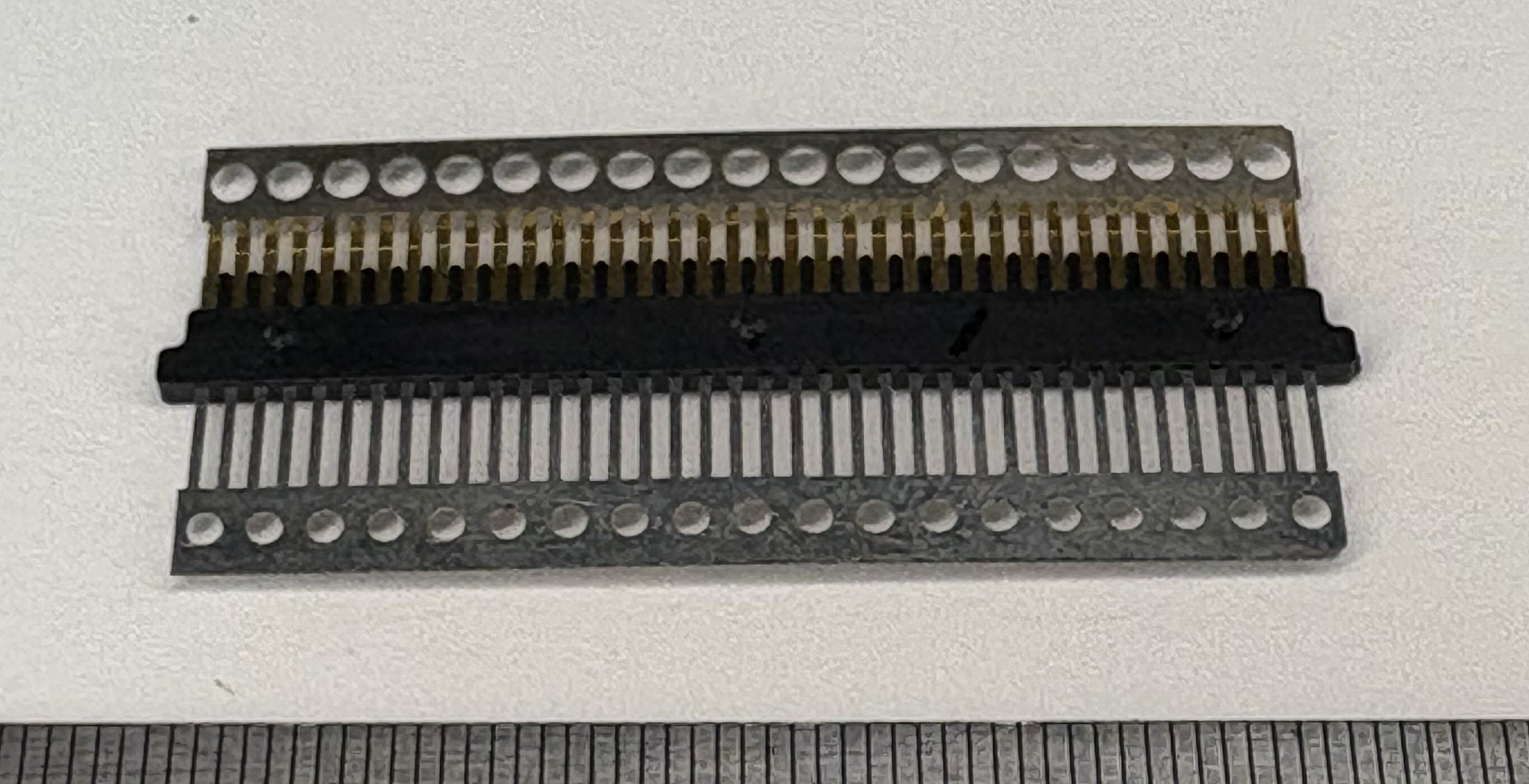
The photograph shows electronic components for the information equipment industry, manufactured using hoop forming.
Although these are legacy components, advanced precision mold technology is utilized.
Material: PPS + phosphor bronze (terminals)
Based on the design and manufacturing of press dies and engineering plastic molds, we provide an integrated production process within the same facility, from terminal press processing to insert molding.
IATF16949 certified
Please entrust us with stable mass production molding of information equipment components.
~ Technology is Beautiful ~ Shinshu Yoshino Electric Co., Ltd.
The photograph shows electronic components for the information equipment industry, manufactured using hoop forming.
Although these are legacy components, advanced precision mold technology is utilized.
Material: PPS + phosphor bronze (terminals)
Based on the design and manufacturing of press dies and engineering plastic molds, we provide an integrated production process within the same facility, from terminal press processing to insert molding.
IATF16949 certified
Please entrust us with stable mass production molding of information equipment components.
~ Technology is beautiful ~ Shinshu Yoshino Electric Co., Ltd.
6 Processes
SPM (Strokes Per Minute): Up to 17

Thickness compatibility: 1.0 to 4.0 mm
Material: Up to SPH590
SPM (Strokes Per Minute): 30 to 40

Automated Labor-Saving Line

SPM 40-50
Thickness 0.8-3.2

80t × 5 Continuous THL Line
150t × 5 Continuous RY Line

Material ~ SPH590
SPM (Strokes Per Minute): 30 to 40
Plate Thickness: 0.55 to 3.2 mm

Automated Line

Automated Line
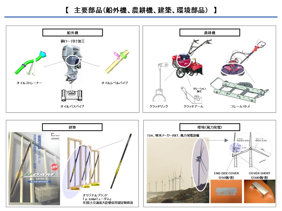
We have experience in the design and manufacturing of outboard motors (brazing), agricultural machinery (various frames and operational mechanism development), and construction materials.
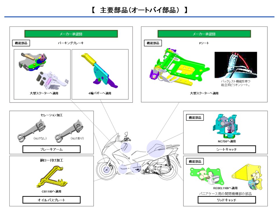
We have experience in the design and manufacturing of motorcycle parts.
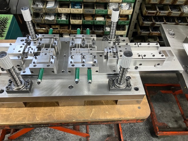
This time, we introduce the “piercing die” used at Apollo Kogyo.
This die was manufactured for mass-produced automotive components and is designed for long pipe materials.
By piercing multiple holes simultaneously in a single process, it significantly improves productivity as a process-reduction die.
The accuracy achieved is an impressive 1/100 to 1/1000 mm range.
This level of precision is supported by skilled technicians through careful finish grinding and final hand-finishing processes.
Because even the slightest deviation is unacceptable, we implement thorough quality control in die structure design, assembly accuracy, and surface finishing.
The “piercing die,” which serves as the heart of such tooling, is one of the most technically demanding processes in press forming.
We support a wide range of materials including steel, SUS, copper, and titanium.
Clearance design and heat-treatment expertise tailored to each material’s characteristics are essential.
Our facilities include 25t–80t presses, servo presses, and contour measuring machines. We also support special press processing, micro-fabrication, and oil-free processing.
Based in Saitama, we are capable of nationwide and overseas shipments.
If you are looking to achieve process reduction and quality improvement through high-precision dies, please feel free to contact us.
_________________
Apollo Kogyo Co., Ltd.
〒342-002, 2405 Miwanoe, Yoshikawa-shi, Saitama-ken, Japan
TEL: +81-48-981-5156
FAX: +81-48-981-5157
Website: https://www.apollo-kk.co.jp
Contact: Mr. Oda
_________________

Use our ability to make proposals, procure materials and cope with quick delivery when you have no time to spare between testing and mass production! In particular, leave fine, narrow, small, thin and complex leaf springs to us. Example: thin: 0.03, small: rice grain size, narrow: diameter 0.5.
A progressive die with a total of 25 processes, die length of 700mm, and a 150-ton press machine.
Material: SUS304CSP-1/2H (spring steel)
Thickness: t0.3mm
Processing elements included: Blanking, punching (round, square), right-angle bending, hemming, drawing, etc.
The more bending points there are, the exponentially more difficult it becomes to maintain overall precision.
We specialize in precision-demanding stamped parts with a high number of processes, from prototyping to mass production.
For more examples of complex-shaped products, click here:
https://www.kyowa-hearts.com/press/
☆ Frequently Asked Questions
https://www.kyowa-hearts.com/faq/
☆ Equipment Information
https://www.kyowa-hearts.com/setsubi/
☆ Contact & Process from Prototyping to Mass Production
https://www.kyowa-hearts.com/flow/
<Contact Information>
Kyowa Hearts Co., Ltd. – Rumi Sakamoto
■ Address: 1-5-1 Takata-Nishi, Kohoku-ku, Yokohama, Kanagawa, Japan
■TEL:045-593-6116 FAX:045-593-6121
■Official website: https://www.kyowa-hearts.com
Material: Phosphor Bronze C5210R-1/2H, t0.15mm
Outer Diameter: φ2.3mm
Circularity: 0.03mm
At the customer's request, we designed a shape that secures the part inside the hole of the mating component.
For more examples of leaf spring products, click here:
https://www.kyowa-hearts.com/spling/
☆ Frequently Asked Questions
https://www.kyowa-hearts.com/faq/
☆ Equipment Information
https://www.kyowa-hearts.com/setsubi/
☆ Contact & Process from Prototyping to Mass Production
https://www.kyowa-hearts.com/flow/
<Contact Information>
Kyowa Hearts Co., Ltd. – Rumi Sakamoto
■ Address: 1-5-1 Takata-Nishi, Kohoku-ku, Yokohama, Kanagawa, Japan
■ TEL: 045-593-6116 FAX: 045-593-6121
■ Official Website: https://www.kyowa-hearts.com
Material: SUS304CSP
Thickness: t0.15mm
Processing Method: Press processing using progressive dies
It is possible to incorporate various processing elements into a small shape.
This product is a leaf spring with two contact points in different directions within a compact space.
When considering parts for weight reduction, multifunctionality, etc., please provide details regarding space constraints and required functions. We can consider the shape and make proposals.
For more examples of leaf spring products, click here:
https://www.kyowa-hearts.com/spling/
☆ Frequently Asked Questions
https://www.kyowa-hearts.com/faq/
☆ Equipment Information
https://www.kyowa-hearts.com/setsubi/
☆ Contact & Process from Prototyping to Mass Production
https://www.kyowa-hearts.com/flow/
<Contact Information>
Kyowa Hearts Co., Ltd. – Rumi Sakamoto
■ Address: 1-5-1 Takata-Nishi, Kohoku-ku, Yokohama, Kanagawa, Japan
■ TEL: 045-593-6116 FAX: 045-593-6121
■ Official Website: https://www.kyowa-hearts.com
【Product Specifications】
Thickness: 0.05mm
Material: Stainless Steel
Max Width: 2mm
Total Length: 3.6mm
Height: 0.7mm
Processing Method: Press processing using progressive dies
This is a low-load leaf spring designed to minimize applied force.
The die clearance is 2μm, which requires manual fine adjustments beyond the precision of machining tools.
Maintaining quality with minimal burrs is the key to press processing.
For more examples of leaf spring products, click here:
https://www.kyowa-hearts.com/spling/
☆ Frequently Asked Questions
https://www.kyowa-hearts.com/faq/
☆ Equipment Information
https://www.kyowa-hearts.com/setsubi/
☆ Contact & Process from Prototyping to Mass Production
https://www.kyowa-hearts.com/flow/
<Contact Information>
Kyowa Hearts Co., Ltd. – Rumi Sakamoto
■ Address: 1-5-1 Takata-Nishi, Kohoku-ku, Yokohama, Kanagawa, Japan
■ TEL: 045-593-6116 FAX: 045-593-6121
■ Official Website: https://www.kyowa-hearts.com
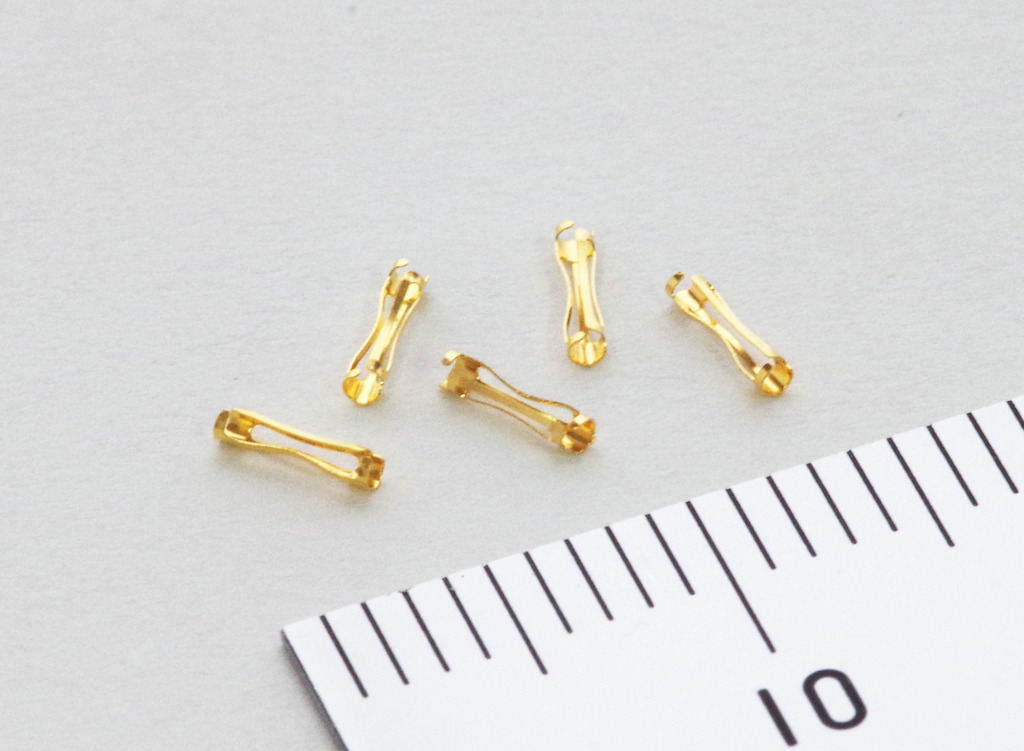
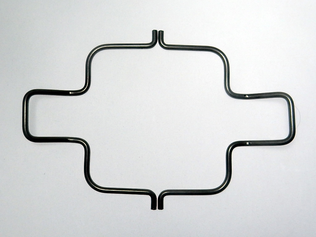
【Product Specifications】
Material: Phosphor Bronze
Thickness: 0.2
Shape:
φ1.9 (1 location)
φ3.7 (3 locations)
Total Length: 14
Application: Antenna Element
Precision in Concentricity & Coaxiality! Complex-Shaped Antenna Element
We successfully achieved concentricity and coaxiality within 0.03 for four interconnected circles of varying diameters, despite their unstable connections.
For more examples of leaf spring products, click here:
https://www.kyowa-hearts.com/spling/
☆ Frequently Asked Questions
https://www.kyowa-hearts.com/faq/
☆ Equipment Information
https://www.kyowa-hearts.com/setsubi/
☆ Contact & Process from Prototyping to Mass Production
https://www.kyowa-hearts.com/flow/
<Contact Information>
Kyowa Hearts Co., Ltd. – Rumi Sakamoto
■ Address: 1-5-1 Takata-Nishi, Kohoku-ku, Yokohama, Kanagawa, Japan
■ TEL: 045-593-6116 FAX: 045-593-6121
■ Official Website: https://www.kyowa-hearts.com
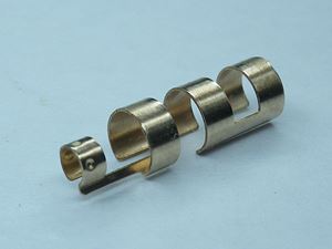
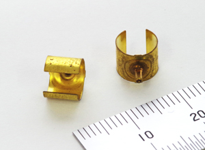
【Product Specifications】
Product Name: Leaf Spring for Socket Contact
Material: C5210R-H (Phosphor Bronze)
Thickness: t0.1
Total Length: 4
Inner Diameter:
Both Outer Sides: φ1.3mm
Center Section: φ0.8mm
Slit Dimensions: Width 0.3 × 6 slots
Roundness Accuracy: Within 0.05
Processing Method: Progressive Curling Processing
Key Explanation
Curling processing refers to the technique of rolling a flat sheet into a cylindrical shape.
The product shown in the image is a tsuzumi (drum) shape, where the center diameter in the length direction is larger than the diameters at both ends. Additionally, it is also possible to process a tawara (barrel) shape, which has a similar structure.
We can handle various spring materials, including phosphor bronze, beryllium copper, and stainless steel (SUS).
We have also successfully developed even smaller-sized components.
For more examples of leaf spring products, click here:
https://www.kyowa-hearts.com/spling/
☆ Frequently Asked Questions
https://www.kyowa-hearts.com/faq/
☆ Equipment Information
https://www.kyowa-hearts.com/setsubi/
☆ Contact & Process from Prototyping to Mass Production
https://www.kyowa-hearts.com/flow/
<Contact Information>
Kyowa Hearts Co., Ltd. – Rumi Sakamoto
■ Address: 1-5-1 Takata-Nishi, Kohoku-ku, Yokohama, Kanagawa, Japan
■ TEL: 045-593-6116 FAX: 045-593-6121
■ Official Website: https://www.kyowa-hearts.com
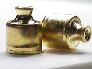
【Product Specifications】
Material: Brass C2680R-1/2H
Thickness: 0.64mm
Height: 4.5mm
Drawn Outer Diameter: φ4.6mm
Necked Section:
Outer Diameter: φ1.6mm
Inner Diameter: φ0.7mm
Processing Method: Progressive Deep Drawing
Key Explanation
Deep drawing is a forming process where pressure is applied to a sheet material to create a seamless, three-dimensional shape. This method is ideal for applications requiring airtightness and high strength.
Creating a necked section in the middle of the product presents a high level of difficulty.
Progressive deep drawing is well-suited for small, high-precision products. However, successful execution relies on experience and know-how that cannot be fully quantified.
For more examples of deep-drawn products, click here:
https://www.kyowa-hearts.com/sibori/
☆ Frequently Asked Questions
https://www.kyowa-hearts.com/faq/
☆ Equipment Information
https://www.kyowa-hearts.com/setsubi/
☆ Contact & Process from Prototyping to Mass Production
https://www.kyowa-hearts.com/flow/
<Contact Information>
Kyowa Hearts Co., Ltd. – Rumi Sakamoto
■ Address: 1-5-1 Takata-Nishi, Kohoku-ku, Yokohama, Kanagawa, Japan
■ TEL: 045-593-6116 FAX: 045-593-6121
■ Official Website: https://www.kyowa-hearts.com
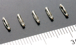
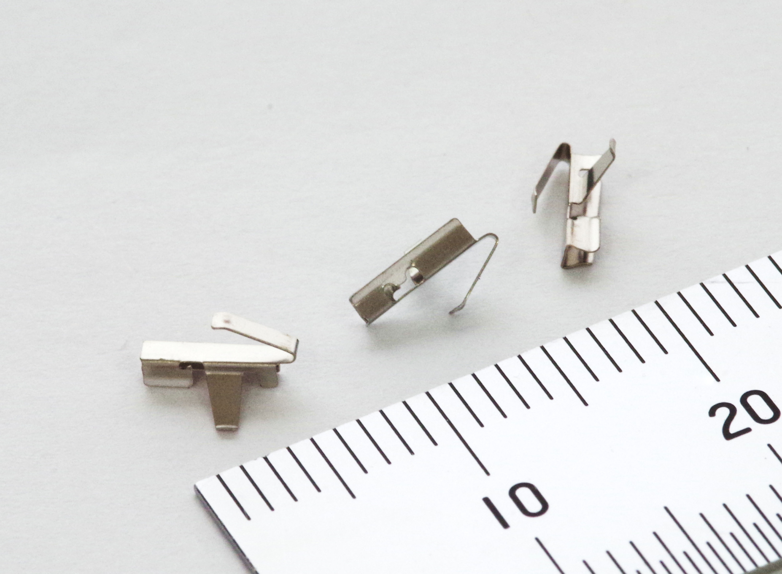
Our company specializes in manufacturing components using micro-slit processing, micro-curling processing, and complex bending processing techniques. We have extensive experience in producing contacts and leaf springs for devices such as mobile phones, computers, and connectors.
Specifications
Material: C1720R-H
Thickness: t0.15mm
Inner Diameter of Both Narrow Ends: φ0.75±0.02mm
Outer Diameter of the Center (Wider Section): φ1.5±0.025mm
Total Length: 5.9±0.05mm
*Additionally, our champion data is:
Material: C5210
Thickness: t0.05mm
Rolled Inner Diameter: φ0.3mm
For more examples of leaf spring products, click here:
https://www.kyowa-hearts.com/spling/
☆ Frequently Asked Questions
https://www.kyowa-hearts.com/faq/
☆ Equipment Information
https://www.kyowa-hearts.com/setsubi/
☆ Contact & Process from Prototyping to Mass Production
https://www.kyowa-hearts.com/flow/
<Contact Information>
Kyowa Hearts Co., Ltd. – Rumi Sakamoto
■ Address: 1-5-1 Takata-Nishi, Kohoku-ku, Yokohama, Kanagawa, Japan
■ TEL: 045-593-6116 FAX: 045-593-6121
■ Official Website: https://www.kyowa-hearts.com
Material / Thickness:
Material: C2680R-1/2H
Thickness: 0.2mm
Processing Details / Precision:
Drawn Section: Outer diameter φ1.2, Height 3mm
Curling Section: Outer diameter φ7mm
Key Points in Progressive Die Manufacturing:
Ensuring that the φ1.2, Height 3mm narrow-drawn section is processed without tearing.
Designing the curling process to achieve roundness without using a core metal.
Key Points in Press Processing:
Proper handling of scrap from piercing the tip of the drawn section.
For more examples of deep drawing processing, click here:
https://www.kyowa-hearts.com/sibori/
☆ Frequently Asked Questions
https://www.kyowa-hearts.com/faq/
☆ Equipment Information
https://www.kyowa-hearts.com/setsubi/
☆ Contact & Process from Prototyping to Mass Production
https://www.kyowa-hearts.com/flow/
<Contact Information>
Kyowa Hearts Co., Ltd. – Rumi Sakamoto
■ Address: 1-5-1 Takata-Nishi, Kohoku-ku, Yokohama, Kanagawa, Japan
■ TEL: 045-593-6116 FAX: 045-593-6121
■ Official Website: https://www.kyowa-hearts.com
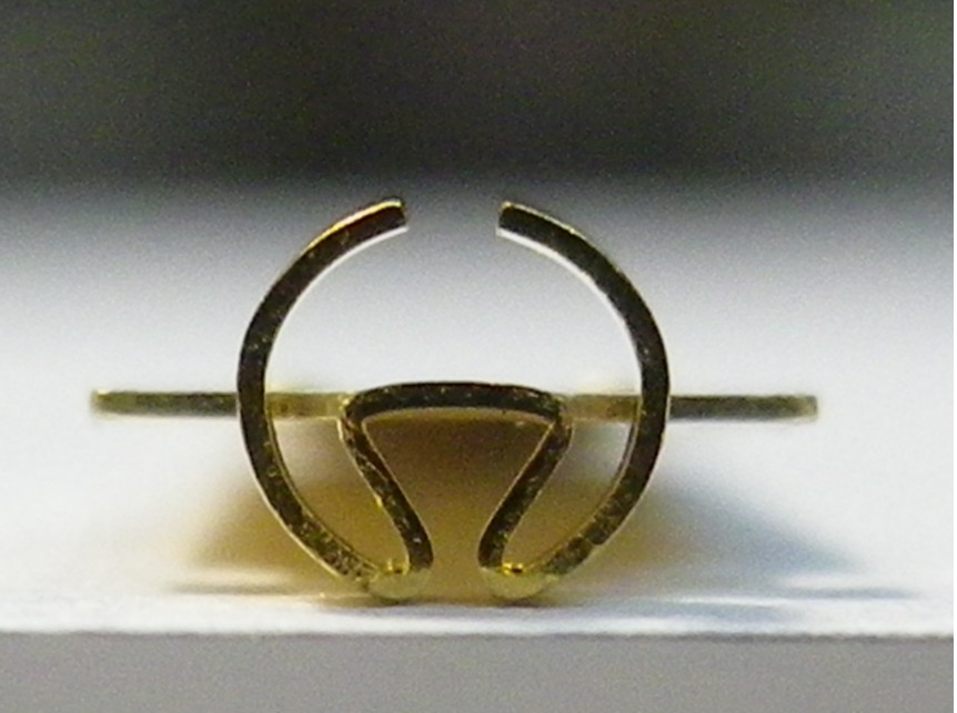
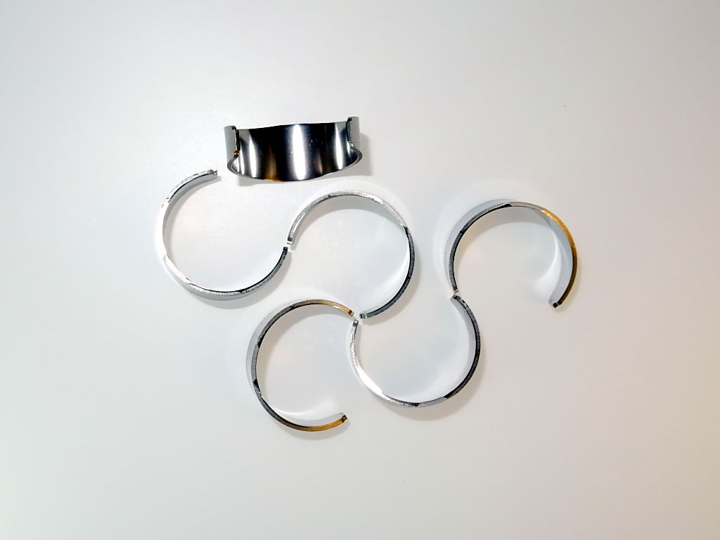
Material: Beryllium Copper C1720R-HM
Sheet Thickness: 0.15 mm
Curling Outer Diameter: φ1.1 mm
Post-Press Processing: Gold Hoop Plating
The product is the round component in the center of the image. The lower three-fifths of the vertical section is shaped into four blades, with their tips evenly and tightly pressed together.
To ensure the four blade tips are securely in contact, various techniques are applied, such as surface pressing around the blades and shaping them into a perfect circular form. The biggest challenge in the curling process is preventing twisting and eccentricity, as the connecting section to the carrier is only 0.3 mm wide and the pre-curling developed length is just 3 mm.
If you are facing difficulties with precision curling processing, please feel free to contact us.
Other Examples of Leaf Spring Products
https://www.kyowa-hearts.com/spling/
Frequently Asked Questions
https://www.kyowa-hearts.com/faq/
Equipment Information
https://www.kyowa-hearts.com/setsubi/
From Inquiry to Prototyping & Mass Production
https://www.kyowa-hearts.com/flow/
Contact Information
Kyowa Hearts Co., Ltd. – Rumi Sakamoto
Address: 1-5-1 Takata Nishi, Kohoku-ku, Yokohama, Kanagawa, Japan
TEL: 045-593-6116
FAX: 045-593-6121
Official Website: https://www.kyowa-hearts.com
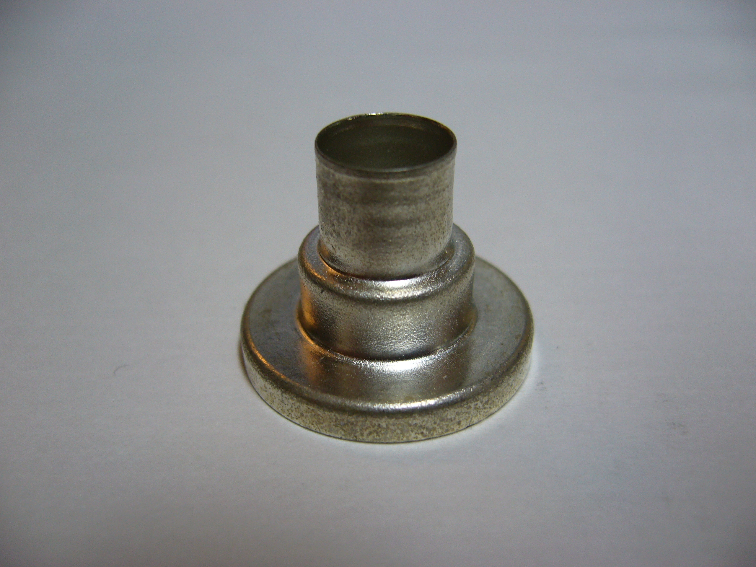
A component produced through multi-stage drawing using a transfer press.
Approximate dimensions: φ8mm - φ12mm - φ22mm, height 17mm.
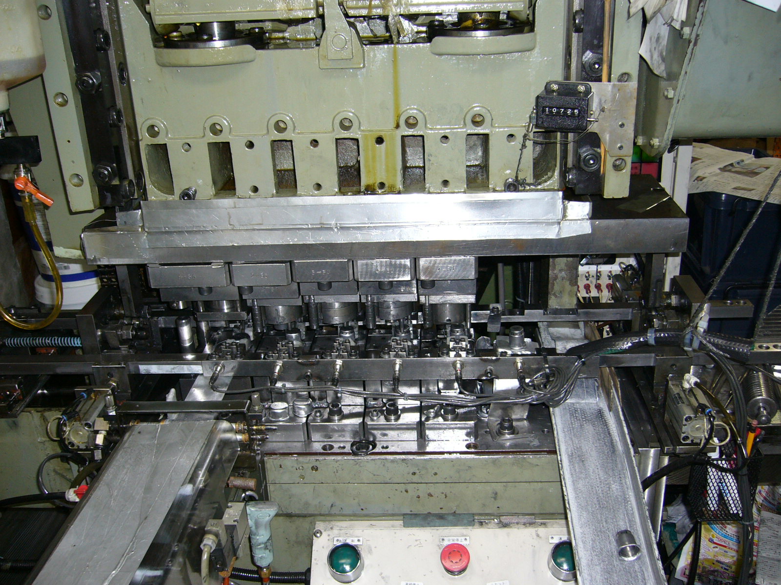
A 20-ton transfer press for small parts.
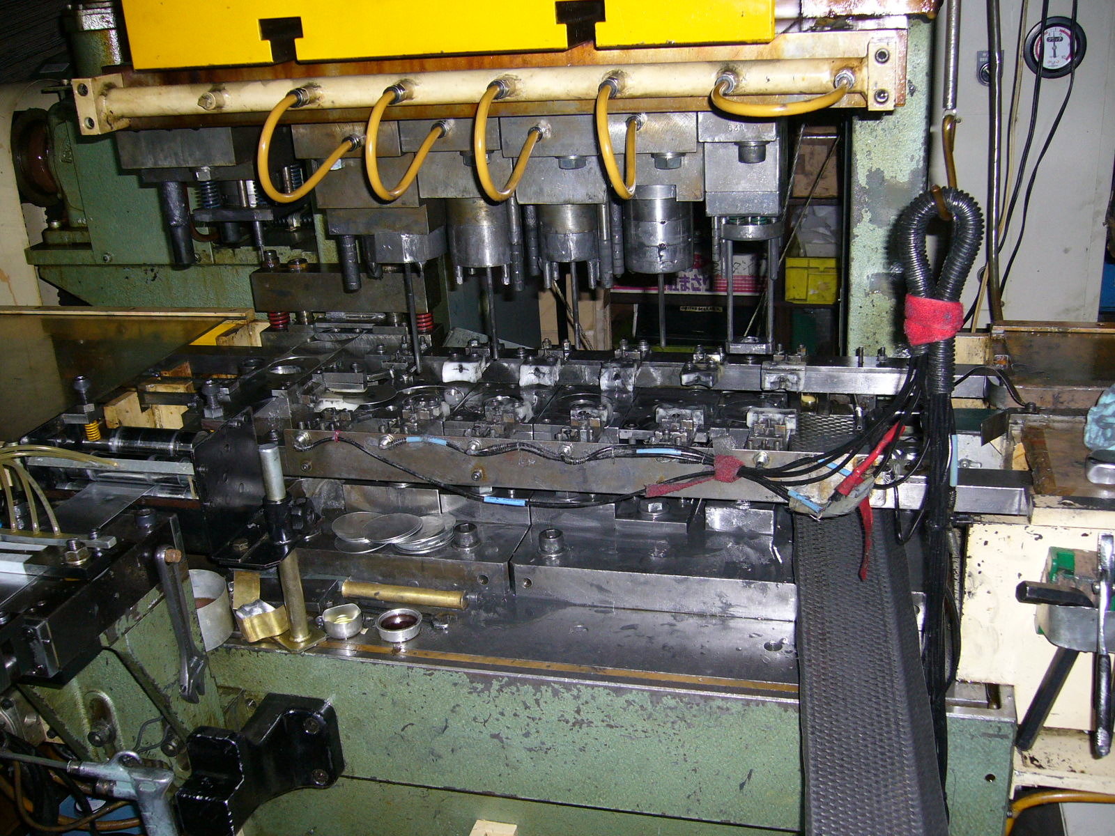
We operate an 80-ton transfer press and produce 500,000 cosmetic exterior parts per month.
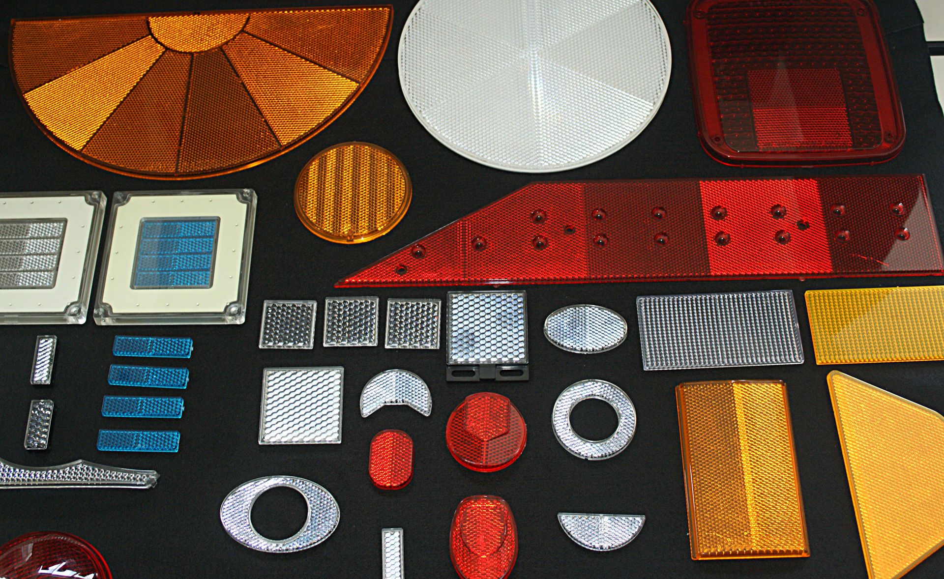
The production of reflex reflectors—especially for photoelectric switch sensors and bicycles—requires advanced design, machining, and assembly techniques. Only a select few companies worldwide possess the expertise to manufacture such precision molds.
Since 1958, when we successfully developed reflector molds using our proprietary technology, we have been supplying molds, standard electroformed products, and molded components to major brand companies both domestically and internationally.

We use SUS444 sheet material.
From a plate thickness of 0.8mm, we iron the wall thickness down to 0.4mm (top surface retains original thickness).
This processing technology is essential to ensure wall thickness uniformity, roundness, and coaxiality.
By employing this method, increased material hardness is achieved, making it widely used in products requiring enhanced airtightness and durability strength.
【Product Details】
Material: SUS444
Plate Thickness: 0.8mm
Industry: Industrial Pneumatic Equipment
Processing Method: Progressive Press
Contact Information
Nissin Precision Machines Co., Ltd. – Head Office
〒146-0095, 2-29-21 Tamagawa, Ota-ku, Tokyo 146-0095, Japan
📞 Tel: +81-3-3758-1901
📧 E-mail: gn_info@nissin-precision.com
Contact Person: F.N
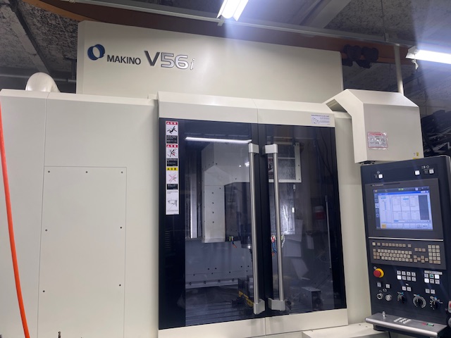
We are pleased to introduce our Vertical Machining Center.
At Nissin Precision, we operate the vertical machining center “V56i” manufactured by Makino Milling Machine Co., Ltd.
The V56i is capable of machining hardened materials. By selecting tools appropriate to the material, virtually any workpiece material can be processed. The machine maintains stable accuracy even during long continuous machining operations.
It also enables complete finishing of aluminum die sets. Thanks to its high precision, circular hole machining previously performed on wire EDM machines can now be processed efficiently on the V56i.
-----------------------------------------------------------------------------------------------
Production Examples (See detailed information on a separate page)
Outer Die Components
Achievable Tolerance: ±0.005 to ±0.01 mm
-----------------------------------------------------------------------------------------------
If you have any challenges related to vertical machining center processing, please feel free to contact us.
❀Contact Information❀
Nissin Precision Machines Co., Ltd. – Head Office
〒146-0095, 2-29-21 Tamagawa, Ota-ku, Tokyo 146-0095, Japan
TEL: +81-3-3758-1901
E-mail: gn.info@nissin-precision.com
Website: https://www.nissin-precision.com/products/precisiondie/
Contact Person: M.H
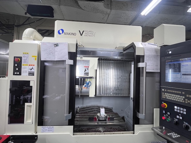
This time, we are pleased to introduce our vertical machining center.
At our company, we use the “V33i” vertical machining center manufactured by Makino Milling Machine Co., Ltd..
Compared to the V56i, the V33i features a different stroke range and excels in high-speed machining, maintaining stable accuracy even during long-hour operations. In comparison with the V56i, it is mainly suited for small to medium-sized workpieces.
----------------------------------------------------------------------------------------------
Production Example (see details on a separate page!)
・Rough machining of flange
・Material: SKD11
・Rough machining is performed from cylindrical stock, taking approximately 5 hours.
----------------------------------------------------------------------------------------------
If you have any concerns regarding vertical machining center processing, please feel free to contact us!
❀ Contact Information ❀
Nissin Precision Co., Ltd. Head Office
2-29-21 Tamagawa, Ota-ku, Tokyo 146-0095
TEL: 03-3758-1901
E-mail: gn.info@nissin-precision.com
Related URL: https://www.nissin-precision.com/products/precisiondie/
Person in charge: M.H
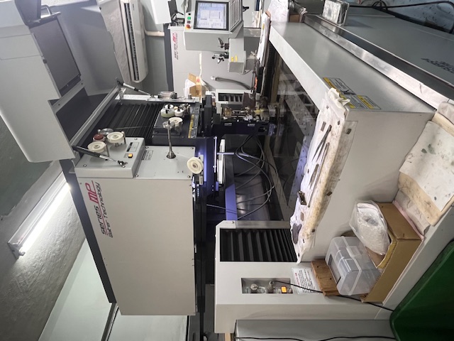
This time, we are pleased to introduce our wire electrical discharge machine (Wire EDM).
At our company, we use the “MP2400 Series” wire EDM manufactured by Mitsubishi Electric.
It allows multiple workpieces to be set at once for long continuous machining, enabling non-stop operation overnight and on weekends.
Fine wire machining is also supported, using wire diameters from φ0.05 to φ0.2 mm. We have a proven track record of machining complex geometries with very tight tolerances, such as ±0.002 mm. In principle, any electrically conductive material can be processed.
-----------------------------------------------------------------------------------------------
Production Example (see details on a separate page!)
・DIE
・Material: WC VF12
・Tolerance: ±0.003
・Wire diameter used: φ0.07
-----------------------------------------------------------------------------------------------
We have three wire EDM machines in operation, striving to achieve high precision and stable quality.
If you have any challenges related to wire EDM machining, please feel free to contact us!
❀ Contact Information ❀
Nissin Precision Machines Co., Ltd. Head Office
〒146-0095, 2-29-21 Tamagawa, Ota-ku, Tokyo, Japan
TEL: 03-3758-1901
E-mail: gn.info@nissin-precision.com
Related URL: https://www.nissin-precision.com/products/precisiondie/
Person in charge: M.H

This time, we are pleased to introduce our high-precision CNC coordinate measuring machine (CMM).
At our company, we use the “STRATO-APEX” manufactured by Mitsutoyo Corporation to measure die components.
While this measuring system represents a significant investment, it delivers measurement accuracy that truly justifies its value. For a company like ours that handles precision die components, it is an indispensable piece of equipment.
This CMM is equipped with several measurement software programs.
One of the programs we frequently use is “CAT1000S,” which includes advanced free-form surface measurement functions. By importing 3D CAD data, the software compares measured points with design data and automatically calculates alignment to minimize deviation, enabling highly accurate and efficient measurements.
Currently, our younger engineers are actively utilizing this function to measure components with a wide variety of complex geometries.
A more detailed explanation of our measurement methods will be provided on a separate page.
❀ Contact Information ❀
Nissin Precision Machines Co., Ltd. Head Office
〒146-0095, 2-29-21 Tamagawa, Ota-ku, Tokyo, Japan
TEL: 03-3758-1901
E-mail: gn.info@nissin-precision.com
Related URL: https://www.nissin-precision.com/products/precisiondie/
Person in charge: M.H
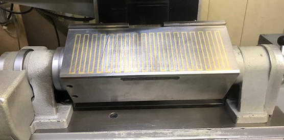
Today, we are pleased to introduce our original in-house product: the “Sine Bar Chuck”, a tilting electromagnetic chuck designed for grinding applications.
At Nissin Precision, we develop functional expansion tools that we ourselves find useful in die manufacturing and supply them to industry professionals.
Below are the key features we would like to highlight:
1. Easy, Fast, and Accurate Angle Setting
⇒ A sine bar is built into the shaft, allowing any desired angle to be quickly and precisely set using gauge blocks.
2. One-Touch Locking Mechanism
To address the common drawback of conventional tilting chucks—dimensional deviation caused during shaft tightening—we developed an indirect clamping mechanism.
This innovation ensures high accuracy with a simple lever operation and allows locking in just a few seconds.
3. High-Precision Shaft and Bearings
⇒ The accuracy during locking is ensured by the “high-precision shaft and bearings.” The shaft is made of special steel, and the bearing incorporates over a hundred steel balls, designed to eliminate play and maintain stable precision.
Product Lineup
Air-cooled type: HSG-315 / 270
Water-cooled type: HSGC-315 / 270
Electrode pitch options are available in both standard and micro-pitch types.
For detailed specifications, please visit our website:
https://www.nissinprecision.com/products/original/sinebarchuck/
We also use the Sine Bar Chuck in our own grinding operations.
If you have any inquiries, please feel free to contact us.
❀ Contact Information ❀
Nissin Precision Machines Co., Ltd. – Head Office
〒146-0095, 2-29-21 Tamagawa, Ota-ku, Tokyo, Japan
TEL: +81-3-3758-1901
E-mail: gn.info@nissin-precision.com
Website: https://www.nissin-precision.com/products/precisiondie/
Contact Person: M.H
Today, we are pleased to introduce our in-house product: the rotary-type electromagnetic chuck, the “Rotary Chuck.”
This product, like the previously introduced Sine Bar Chuck, was developed for professionals engaged in die manufacturing, and is designed to significantly improve both work efficiency and machining accuracy.
By using the Rotary Chuck, rotational machining can be performed easily and with high precision. When used together with the Sine Bar Chuck, processes that were previously time-consuming can now be carried out more efficiently while maintaining high accuracy.
Thanks to its compact and lightweight design, setup changes and attachment/detachment are smooth. It reduces operator workload on-site while expanding machining capabilities.
When combined with the optional V-block, convex and concave machining of round components such as punches and dies (φ10–35mm) can be achieved with excellent workability.
In addition, the Rotary Chuck alone ensures high precision in the 1/1,000mm range (based on in-house measurements).
Furthermore, it adopts a waterproof protection structure rated IP63, making it suitable for both dry and wet machining environments, allowing safe and reliable operation in the field.
For more details, please visit our website:
https://www.nissinprecision.com/products/original/rotarychuck/
We also offer free rental of the Rotary Chuck. Please feel free to contact us.
❀ Contact Information ❀
Nissin Precision Machines Co., Ltd. Head Office
〒146-0095, 2-29-21 Tamagawa, Ota-ku, Tokyo, Japan
TEL: 03-3758-1901
E-mail: gn.info@nissin-precision.com
Related URL: https://www.nissin-precision.com/products/precisiondie/
Person in charge: M.H
Wire springs are essential components for energy storage and vibration absorption in machinery, widely used in applications ranging from automotive to medical devices.
[Features]
• Versatile material compatibility: Stainless steels including SWC, 60C, and SUS304
• Advanced processing techniques: Bending and punching of wire and shaped materials
• Broad application range: From precision instrument parts to everyday items
• Flexible production: Capable of small-lot production for various product types
[Applications]
• Automotive parts
• Medical devices
• Electronic device terminals
• Industrial and agricultural machinery
• Precision instrument components
[Nippon Forming's Strengths]
• Micro-processing technology
• Expertise in complex shape manufacturing
• Comprehensive quality control
We specialize in manufacturing wire springs tailored to our customers' specific requirements. Our production process ensures consistent quality control from material selection through to final production.
We also specialize in precision processing of wire and strip materials, accommodating diameters from 0.1 to 5mm. Our NC-controlled manufacturing enables complex shape production.
For inquiries regarding wire springs or custom orders, please don't hesitate to contact us.
[Company Information]
Nippon Forming Co., Ltd.
Headquarter & Main Factory: 1-23-2 Kanamachi, Katsushika-ku, Tokyo
Tsukuba Factory: 2924 Ujikai, Ishioka-shi, Ibaraki
https://www.forming.jp/eng/
Nippon Forming specializes in metal bending processing.
We perform high-precision processing for plate springs, wire springs, and metal fittings.
[Features]
• Adaptability to diverse shapes and materials
• Technical capability to meet complex requirements
• Precise bending and punching processing
• Capabilities from small-lot to mass production
[Main Products]
• Contact terminals
• Stoppers
• Various metal fittings
[Applications]
• Precision electronic devices
• Automotive parts
• Industrial equipment
• Communication devices
• Medical equipment
[Processing Technology]
• Bending process considering material characteristics
• Combination with punching process
• Compatibility with various materials (stainless steel, brass, shaped materials, etc.)
[Nippon Forming's Strengths]
• Product supply to a wide range of fields
• Consistent support from prototyping to mass production
• Continuous technological improvement
For inquiries about metal processing, please contact us. We manufacture high-quality products, accommodating complex shapes and special materials.
We are a specialized manufacturer of precision-processed wire and strip materials.
We work with various materials ranging from 0.1 to 5mm. Complex shapes are achievable through NC control.
[Company Information]
Nippon Forming Co., Ltd.
Headquarter & Main Factory: 1-23-2 Kanamachi, Katsushika-ku, Tokyo
Tsukuba Factory: 2924 Ujikai, Ishioka-shi, Ibaraki
https://www.forming.jp/eng/

Nippon Forming specializes in producing high-precision parts with complex shapes using multi-forming machines.
[Features]
• Capability to handle complex shapes
• Precision processing of materials with springback
• Flexible production from small to large quantities
[Product Overview]
• Automatic bending and forming of metal wire and sheet materials
• Support from prototyping to mass production
[Applications]
• Lighting fixture components
• UV equipment components
• Automotive parts
• Agricultural equipment parts
• Power system components
• Power distribution equipment parts
[Processing Materials]
• Nickel-plated hard steel wire
• Stainless steel wire for springs
• Various iron wires (ordinary, annealed, water-drawn, nickel-plated)
• Nickel silver, Inconel, Kovar wire
• SUS316 and others
[Nippon Forming's Strengths]
• Multi-product small-lot production
• Integrated service from material selection to finishing
• Design considering springback
Nippon Forming meets the processing needs for complex shapes and special materials, providing high-precision and durable products. We flexibly accommodate from small lots to mass production, so please feel free to contact us.
Nippon Forming is a specialized manufacturer of precision-processed wire and strip materials.
We work with various materials ranging from 0.1 to 5mm in diameter. Complex shapes are achievable through NC control.
[Company Information]
Nippon Forming Co., Ltd.
Headquarter & Main Factory: 1-23-2 Kanamachi, Katsushika-ku, Tokyo
Tsukuba Factory: 2924 Ujikai, Ishioka-shi, Ibaraki
https://www.forming.jp/eng/
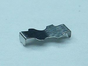
By crimping the pins using a progressive die, it becomes possible to minimize the use of expensive materials.
This component is a spring for a spacer.
Component size: 4mm
Plate thickness: 0.2mm
Processing method: Stainless steel is processed using a 45-ton press.

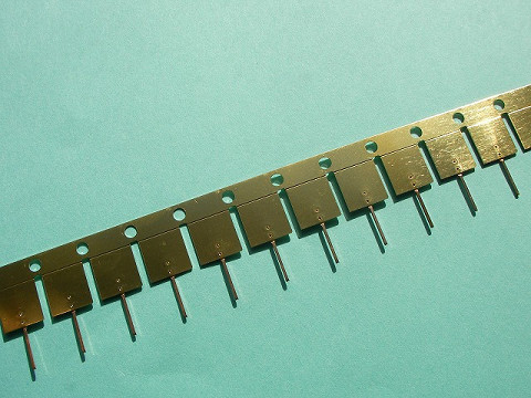
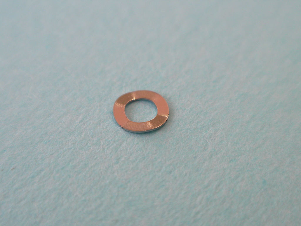
This product is manufactured using C1100 material with a sheet thickness of 1.6 mm.
From the initial shape to the final product shape, no machining processes are used.
Dimensions: 9 × 9 × t3.4
Tolerance: ±0.1
Post-press process: Nickel plating
Application: Power diodes designed to meet a wide range of needs, from general consumer and industrial equipment to automotive and electrical applications.
⁂ Dimensional and shape accuracy are ensured through in-process and final inspections using coordinate measuring machines (CMMs) and non-contact laser measuring devices, guaranteeing product functionality and reliability.
With many years of experience and proven technical expertise, we support manufacturing tailored to our customers’ needs.
※For inquiries, please contact us at the details below.
ꕤ︵ꕤ︵ꕤ︵ꕤ︵ꕤ︵ꕤ
Ohnuki Kogyosho Co., Ltd.
Sales & Production Control Department
Takuya Osumi / Miu Wada
📩 infoh@ohnuki.co.jp
📞 0294-53-3821
ꕤ︵ꕤ︵ꕤ︵ꕤ︵ꕤ︵ꕤ
[Outer Perimeter Warizaki] Method
A three-dimensional integrally molded piece is formed from a single plate.
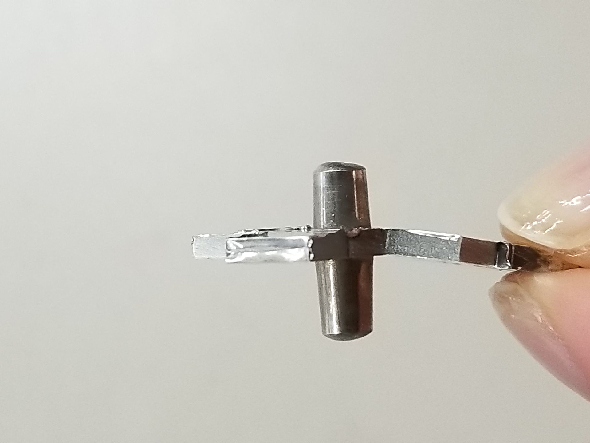
Achieves solid projections on both sides of a thin plate (photo held by hand) in a single press operation.
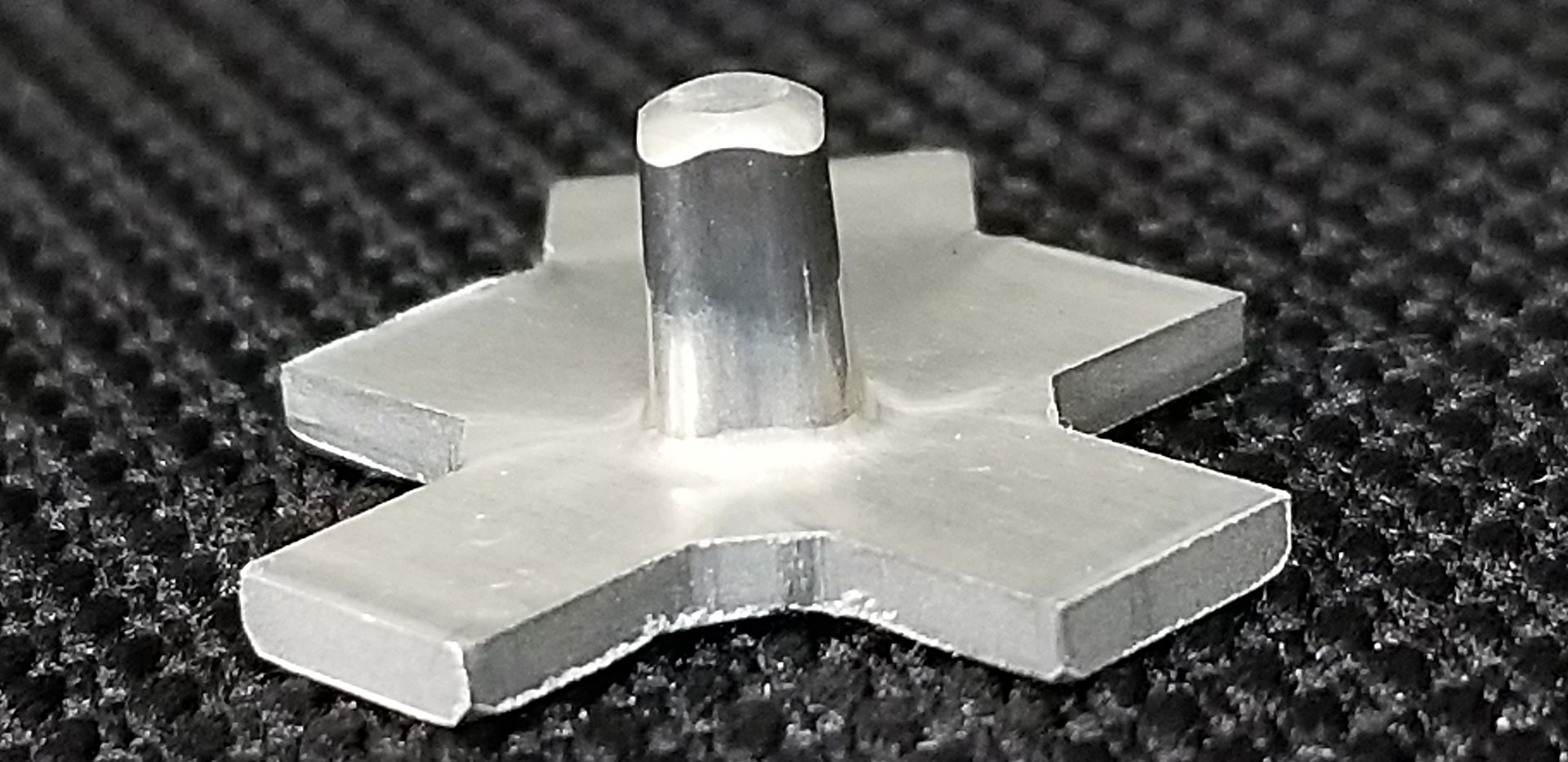
ONLY ONE Processing Technology [Turm Method]
Achieves solid rectangular column projections on a thin plate in a single process.
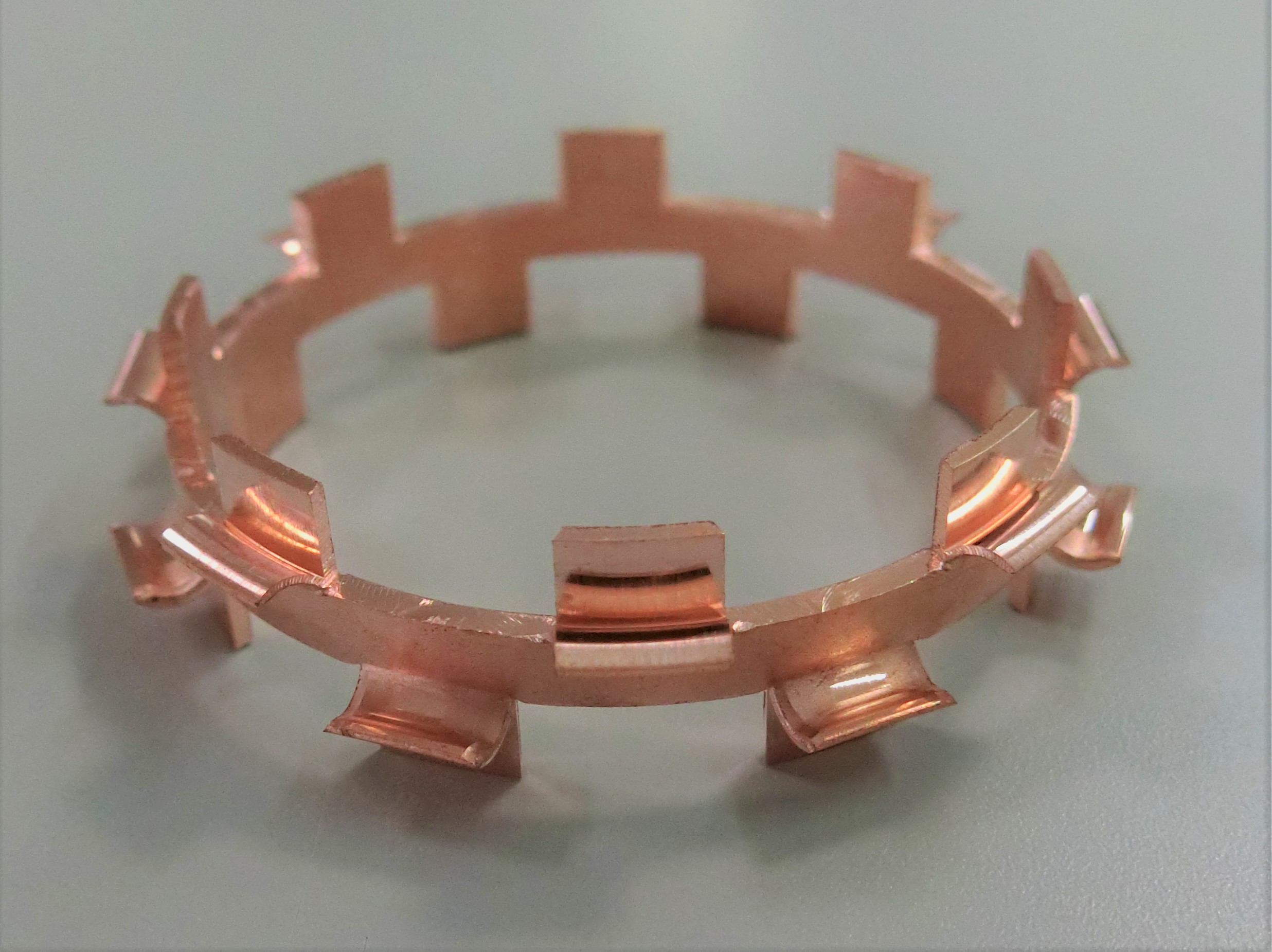
ONLY ONE Processing Technology [Split Method]
Splits a plate into three parts.
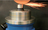
The photo shows the hardening station in a motor shaft gear induction hardening machine.
Two shafts are induction heated simultaneously by a line coil.
The shafts, each approximately 10mm in diameter and 100mm in length,
are induction hardened in 16 seconds per cycle.
Using our original semi-coil line coil and rotating one-shot hardening method,
this machine achieves a casing along the shaft outer diameter.
※ Ring coil scan hardening requires longer cycle time, can cause overheating
of the corners, and have shallow case depth at the curved sections.
By exchanging the coils and jigs, this machine can process up to 20 shaft models.
~Shaft Gear Induction Hardening Machine ② Line Coil Automobile
Machine Parts IH Heat Treat~
The photo shows our motor rotation shaft gear hardening machine.
This machine simultaneously hardens two Φ10, 100mm shafts
with a cycle time of 16 seconds.
Installed in-line at a motor production plant, the machine receives
the workpieces from the previous process,
automatically hardens the workpieces, and sends them to the next process.
The workpieces are loaded from the port to the left (near the bottom
of the control panel).
They are hardened at the left-hand station, after-cooled at the center station,
and air blowed at the right-hand station, before being unloaded from the port
on the right.
To achieve hardening quality and short cycle time, the workpiece,
a multi-diameter shaft. and is hardened by one-shot hardening
using our semi-open line coil to create a even casing along the workpiece's
outer diameter.
※In comparison, scan hardening using a ring coil requires longer cycle time,
can cause overheating at the shaft corners, and have insufficient case depth
at the curved parts of the shaft.
By exchanging the coils and jigs, this machine can several different types
of workpieces.


